EasyManua.ls Logo

Nibe F205P - Heating System Maintenance; Filling the Heating System

Nibe F205P
8 pages
To Next Page IconTo Next Page
To Previous Page IconTo Previous Page
Loading...
F205P
Maintenance routines
LEK
2
3
1
20 100
40 80
60
°C
0 120
T
G
Art.nr. 611830
( )
( )
( )
20 100
40 80
60
ϒC
0 120
T
G
2
1
bar
3
0 4
T
G
Art.nr. 611830
20 100
40 80
60
ϒC
0 120
T
G
2
1
bar
3
0 4
T
G
Art.nr. 611830
20 100
40 80
60
ϒC
0 120
T
G
2
1
bar
3
0 4
T
G
LE
K
LE
K
LE
K
( )
Auto
1
2
3
1
20 100
40 80
60
C
0 120
T
G
2
1
bar
3
0 4
T
G
( )
Auto
1
2
3
1
20 100
40 80
60
C
0 120
T
G
2
1
bar
3
0 4
T
G
( )
Auto
1
2
3
1
20 100
40 80
60
C
0 120
T
G
2
1
bar
3
0 4
T
G
Å
te
r
-
ledning
radiatorer
8
31 32
94
86
30
Fram-
ledning
radiatorer
9
11
18
59
78
27
36
33
20
58
108
52
96
109
97
42
62
48
63
87
65
99
Åter-
ledning
radiatorer
k.v.v.v.
41
35
51
80
71
50
84
98
85
43
53
1
k.v.
v.v.
Blaha b
lah
a
oc
h anna
t
trams
Å
te
r
-
ledning
radiatorer
Blaha
b
lah
a
o
c
h anna
t
trams
103
88 6
25
104
148
73
95
19
47
66
149
151
74 150
Å
te
r
-
le
dnin
g
ra
dia
t
ore
r
8
31 32
86
30
11
18
59
78
27
36
33
20
58
108
52
96
109
97
42
62
48
63
87
65
99
41
51
80
50
43
k.v.
v.
v.
B
l
aha
b
l
ah
a
o
c
h
ann
a
t
t
rams
Å
t
e
r
-
l
e
dn
ing
ra
di
a
tore
r
Bl
ah
a
b
l
a
h
a
oc
h anna
t
trams
25
104
148
47
149
151
74 150
7 43
94
1
88 6
7 43
6
3
9
6
3
Å
te
r
-
le
dnin
g
ra
dia
t
ore
r
k.v.
v.
v.
B
l
aha
b
l
ah
a
o
c
h
ann
a
t
t
rams
Å
t
e
r
-
l
e
dn
ing
ra
di
a
tore
r
B
l
ah
a
b
l
a
h
a
oc
h anna
t
trams
16
44
70
35
16
44
70
5
19
5
14952
151
150
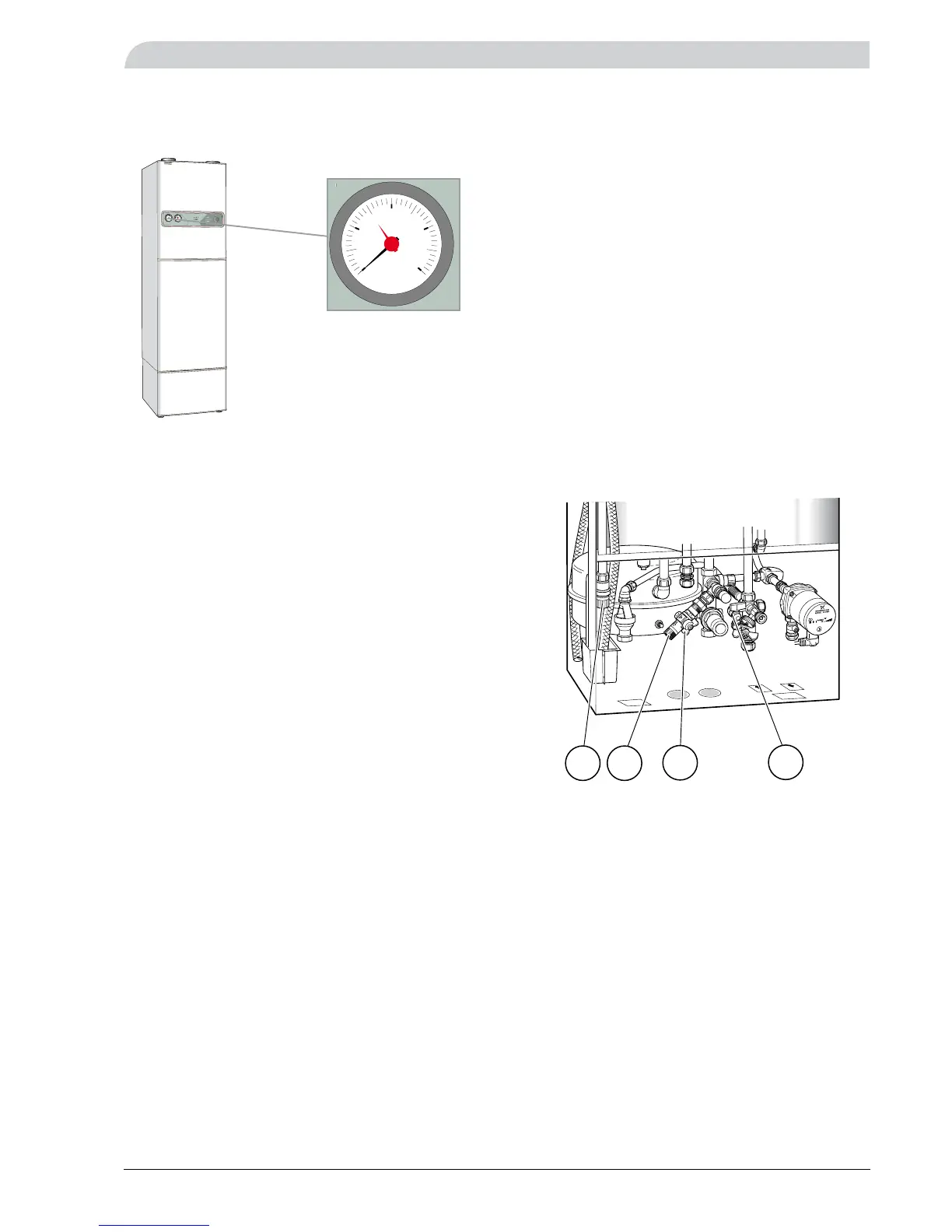
Filling the heating system
1. Connect the supplied flexible hose between connec-
tion (149) and connection (150). Open the filling valve
(151). The boiler part of the heat pump and the radia-
tor system can now be filled with water.
2. The pressure indicated on the pressure gauge will
be seen to increase after a time. When the pressure
reaches 1.0 bar, you should close the filling valves
(149) and (151).
3. The temperature of the water will increase after a
time, with an accompanying increase in the pressure.
4. If the pressure is too high, you can reduce it by rotat-
ing the safety valve for the heating system (52).
5. The flexible hose between connection (149) and con-
nection (150) must not be connected during opera-
tion. Remove it before the heat pump is taken into
service.
The pressure gauge indicates the pressure in the heating
system. The pressure should be between 0.5 and 1.5 bar.
Pressure gauge

Other manuals for Nibe F205P

Related product manuals