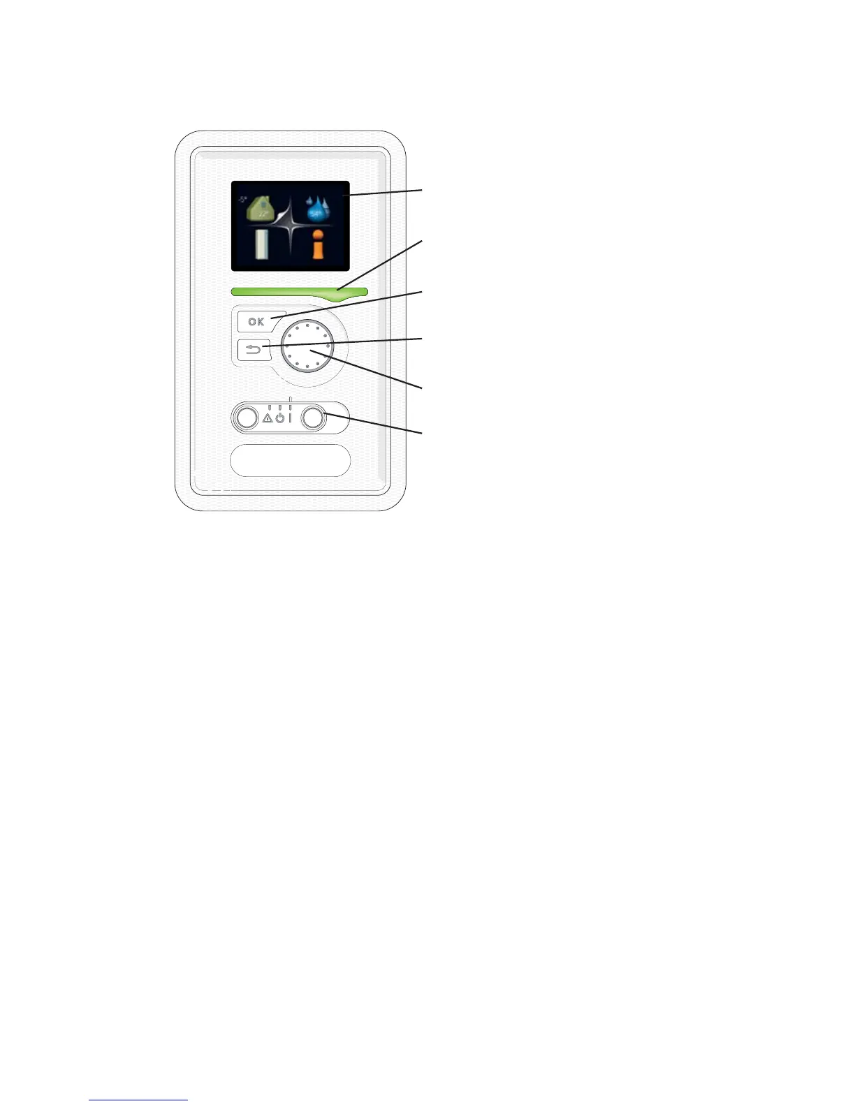
Display unit
$
%
&
'
(
)
'LVSOD\
6WDWXV ODPS
2. EXWWRQ
%DFN EXWWRQ
&RQWURO NQRE
6ZLWFK
,1'225 &/,0$7(
+($7 3803 ,1)2
+27 :$7(5
)
There is a display unit behind the heat pump door, which is used to commu-
nicate with F750. Here you:
႑
switch on, switch off or set the heat pump in emergency mode.
႑
sets the indoor climate and hot water as well as adjusts the heat pump
to your needs.
႑
receive information about settings, status and events.
႑
see different types of alarms and receive instructions about how they are
to be rectified.
Display
Instructions, settings and operational information are shown on the
display. The easy-to-read display and menu system, facilitates navigation
between the different menus and options to set the comfort or obtain
the information you require.
A
Status lamp
The status lamp indicates the status of the heat pump. It:
႑
lights green during normal operation.
႑
lights yellow in emergency mode.
႑
lights red in the event of a deployed alarm.
B
NIBE™ F750Chapter 2 | The heat pump – the heart of the house12
 Loading...