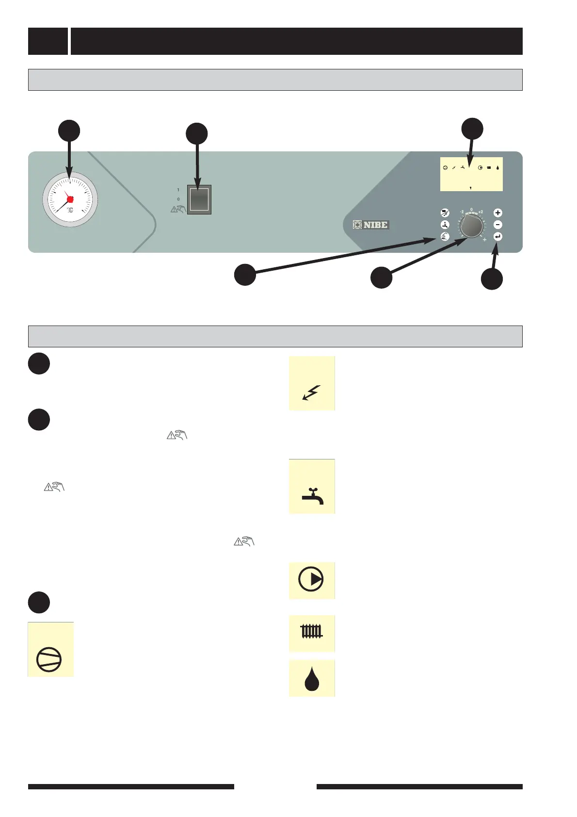
Front panel
VVM 240
4
Pressure gauge
The radiator circuit pressure is displayed here.
Gauge graduation is 0 — 4 bar. Normal pres-
sure is 0.5 1.5 bar with a closed system.
Switch
with three positions 1 - 0 - :
1 Normal mode. All control functions connected.
0 Boiler completely switched off.
Standby. This position is used in the event
of operating disturbances. The immersion
heater output is limited to 6 kW, the circula-
tion pump (16) and charge pump (40) are in
continuous operation.
The switch must not be turned to 1 or “ ”
before filling the boiler with water.
Display
2
1
bar
3
04
A B A B A BI II III
54.1°C
Hotwatertemp.
1.0
13.43
Switch
Pressure gauge
B
Left
keypad
Offset heating
curve
Display
First row:
Compressor symbol
A together with a compressor symbol is
shown when step 1 is operational.
B together with a compressor symbol is
shown when step 2 is operational.
Only a compressor symbol indicates that the
compressor will start, but is blocked as an inter-
nal start condition in FIGHTER 2010 has not
been met, e.g. time condition.
Layout
A
C
B
D
E
Right
keypad
Addition symbol
Indicates when immersion heater is con-
nected. The line indicates which power
step/steps are currently connected.
I 3 kW additional power is connected
II 4.5 kW additional power is connected
III 6 kW additional power is connected
Hot water symbol
Indicates when the Extra hot water function
is active.
A is shown when the 24 hour temperature
increase is active.
B is shown when a time based temperature
increase is activated, for example periodic.
Circulation pump symbol
Shown when the circulation pump is oper-
ational.
Heating system symbols
Shown when house heating is in progress.
Defrosting symbol
Indicates when defrosting of FIGHTER
2010 is in progress.
F
C
Explanation
A