5 – English
English
5
Connection
cascade
Connection
Star
Connection
“combined”
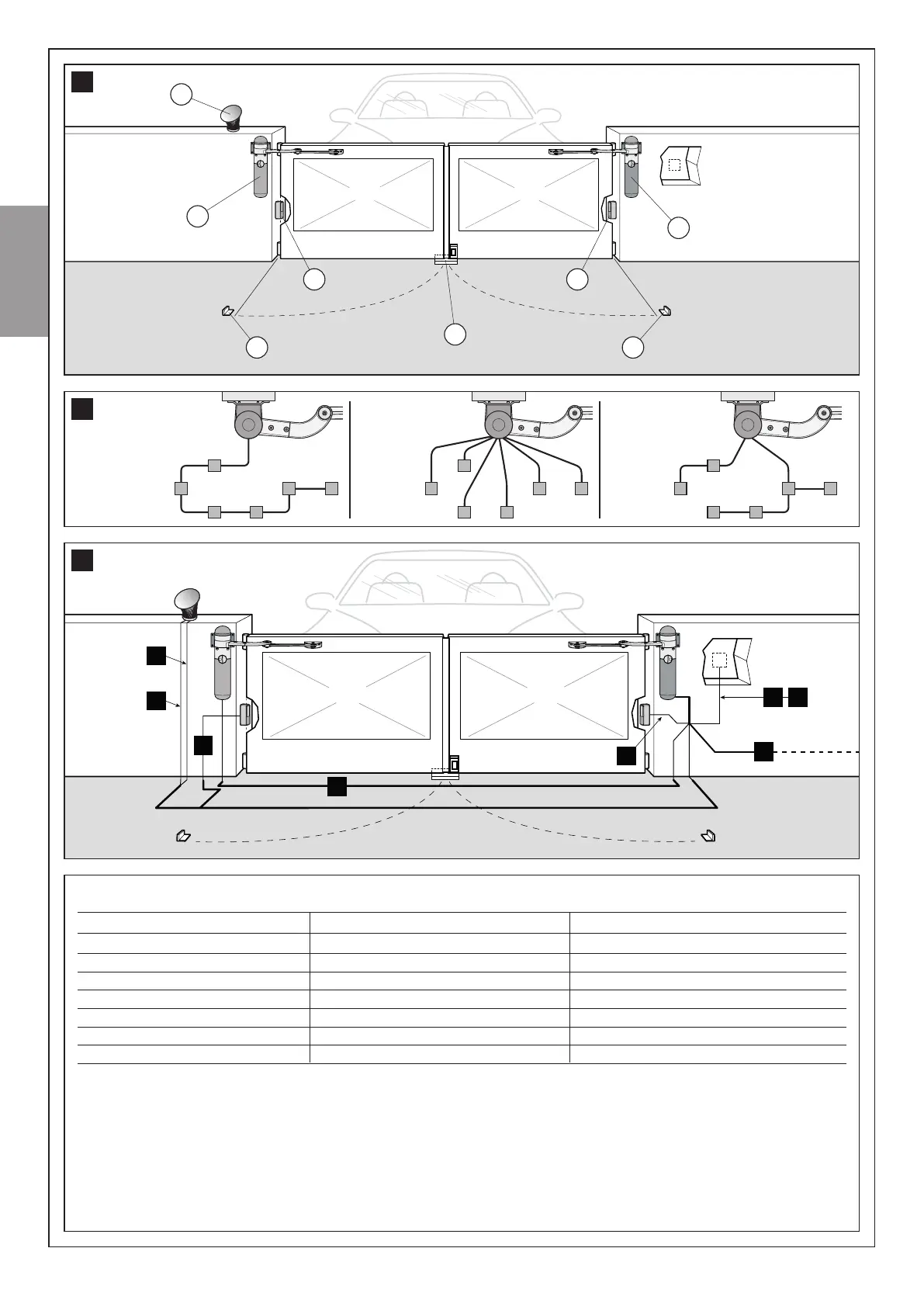
TABLE 2 - Electric cable specications (ref. g. 6 and paragraph 3.3.4)
Connection Type of cable (minimum section values) Max. admissible length
A - Power line cable 3 x 1,5 mm² (note 1) 30 m (note 2)
B - FLASH Flashing light output cable 2 x 0.5 mm² 20 m
C - Radio aerial RG58 shielded cable type 20 m (less than 5 m recommended)
D - BUS input/output (note 4) cable 2 x 0.5 mm² 20 m (note 3)
E - STOP Input cable 2 x 0.5 mm² 20 m (note 3)
F - SbS Input cable 2 x 0.5 mm² 20 m (note 3)
G - Motor output without control unit cable 3 x 1 mm² 10 m
Note 1 - External cable diameter: Maximum 11 mm.
Note 2 - If the poer cable is longer than 30 m, a cable ith a larger section is required (e.g. 3x2.5mm²) and safety earthing is necessary in the
vicinity of the automation.
Note 3 - For these connections (D, E, F) a single cable ith multiple internal ires may be used. This enables grouping of multiple connections:
for example, the STOP and SbS inputs can be connected to the accessory device ith a cable of 4 x 0.5 mm².
Note 4 - For information on ECSBus technology, refer to paragraph 3.3.3
WARNING! – The cables used must be suited to the installation environment: for example, for indoor environments cable types
H03VV-F are recommended, and for outdoor environments, cable types H07RN-F.
E
a
c
e
c
f f
b
d
4
A
B
C
G
D
D
E F
6