English – 20
English
7.2 - LEARNING THE MAXIMUM LEAF OPENING ANGLE
After learning the devices, the control unit must learn the maximum leaf
opening angle, starting from the closing travel stop. Therefore proceed
as follows.
01. In Table 3 identify the diagram that represents the position of the
overlapping leaf and the gearmotor with control unit, present on your
system (these two details are in black on the diagram).
02. On the control unit, wire in jumpers JA and JB, in the same position
indicated alongside the diagram shown in Table 3.
03. Release the gearmotors by means of the special keys (read para-
graph “Manually locking and releasing the gearmotor”) and move the
leafs to mid-travel; then lock the gearmotors again.
04. On the control unit, press and hold P3 until Led P3 starts ashing
quickly; then release the key.
05. Wait the control unit to independently activate a pre-set sequence of
manoeuvres and only intervene in the event of a fault.
Manoeuvre sequence:
1) closure of motor M1 through to mechanical stop; 2)closure of
motor M2 through to mechanical stop; 3) opening of motor M2 and
motor M1 through to the mechanical opening stop; 4) complete clo-
sure of M1 and M2. Caution!
Cases of faults:
A) If the rst manoeuvre of one or both the leafs is not closure, press
P3 to stop the learning phase and control the position of the electric
jumpers JA and JB (see Table 3).
B) If the rst motor to move towards the closing point is not M1, press
P3 to stop the learning phase and check the positions of the electrical
jumpers JA and JB, with reference to Table 3.
C) During the learning phase, if any device trips (photocells, P3
pressed etc.), the learning phase is stopped immediately, and so
must be repeated from phase 04.
06. At the end of the manoeuvre, Led P3 turns off, conrming memo-
risation of the maximum leaf opening angle. Caution! – If the Led
continues to ash this means that there is an error; in this case read
paragraph D - “Troubleshooting”.
Warning – In the future, if one or both opening travel stops are moved,
the entire learning procedure must be repeated.
7.3 - OPERATION PARAMETER SETTINGS
.3.1 - Programming the leaf movement speed
The speed of the leaf during opening or closing may be set by selecting
one of two options: “low speed” or “high speed”.
To program the required option, briey press P2 and check the status of
Led P2: if this turns off, it means that the “low speed” option is set; other-
wise if it turns on it means that the “high speed” option has been selected.
To switch between one option and the other, press P2 again.
WARNING – If the leaf is longer than 1.20 m, heavier than 100 kg and the
gearmotor is installed with the arm shortened the “low speed” option is
recommended. The” high speed” option should only be set for leafs with
shorter lengths and lighter weights.
7.3.2 - Programming the “work cycle”, i.e. the behaviour of the
automation after an opening manoeuvre
After an opening manoeuvre is activated by the user, the automation sets
up for a closing manoeuvre according to the option programmed for this
parameter. Two options are available: “half cycle” or “complete cycle”.
• Half cycle: (factory setting) after an opening manoeuvre is activated
by the user, the leafs remain open until the user activates a closing
manoeuvre (semi-automatic mode).
• Complete cycle: after an opening manoeuvre is activated by the user,
the leafs remain open for a set time interval, after which they are closed
automatically by the control unit (automatic mode). To modify the pause
time, read paragraph B and relative sub-paragraphs.
To program a work cycle, briey press P3 and check the status of Led P3:
if it is off, this means that the “half cycle” is set; if lit, the “complete cycle”
is set. To switch between one option and the other, press P3 again.
7.4 - CHECKING OPERATION OF THE RADIO
TRANSMITTERS
The control unit incorporates a radio receiver for ECCO5 transmitters
(various models). The transmitters supplied are not memorised; therefore,
at the beginning, it is necessary to memorise the FIRST transmitter (Mode
1), with the procedure C.2.
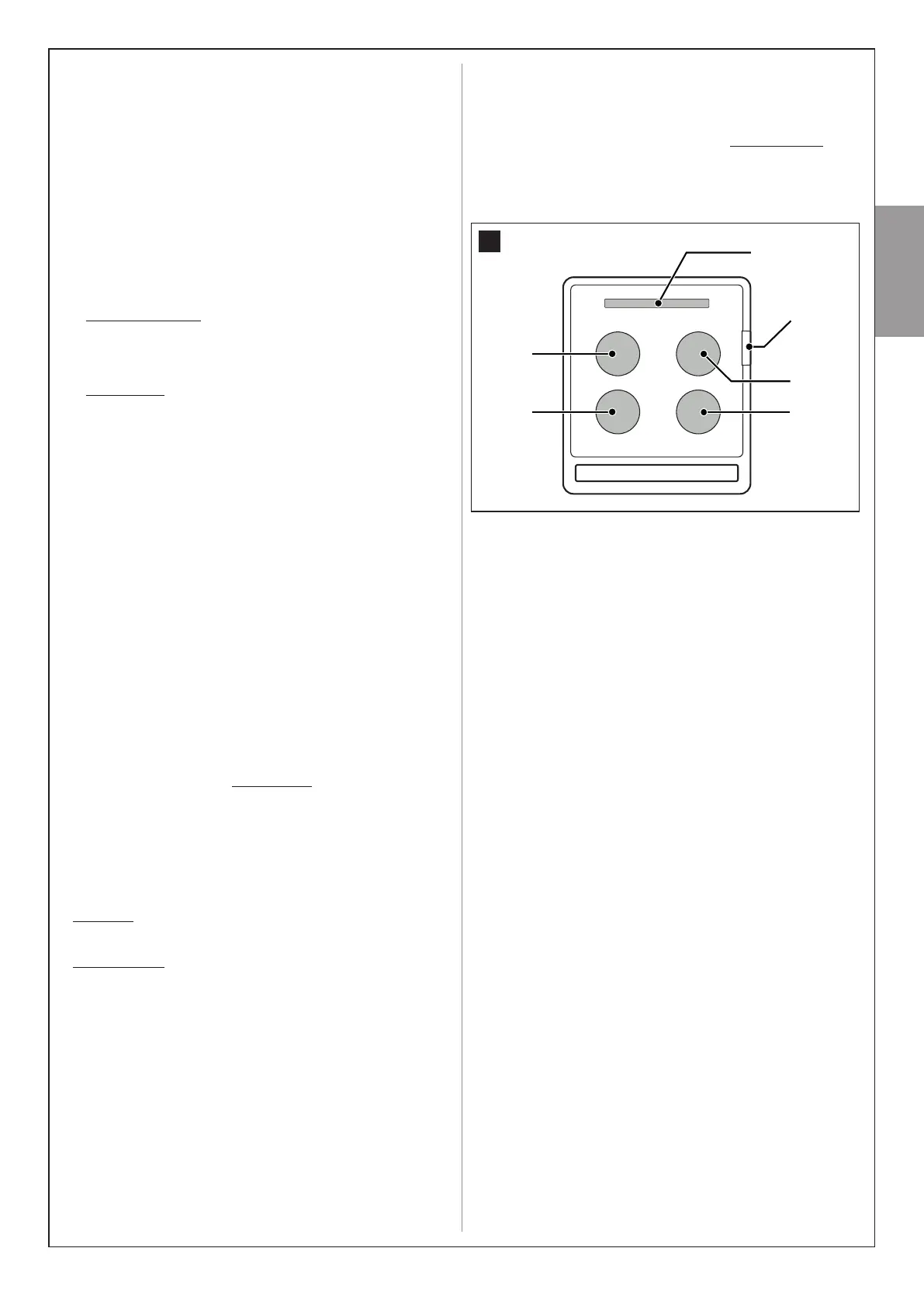
In this manual the transmitter keys are identied with the symbols T1,
T2, T3, T4, T5 (see g. 29). Warning! - The T5 key is not used in this
application.
[A] Led
T5
T2
T4
T3
T1
29
To check operation of the transmitter press a key and at the same time
ensure that the transmitter led [A] ashes and that the automation exe-
cutes the command envisaged for that key.