CBOX1050
Installation and Programming Manual
1313
MX4682 Rev. D ©2021
The 1050 control board operates ONLY on DC power from the battery or from the Main DC Power input. Follow
all safety warnings if installing AC power for conversion to DC for charging purposes or for powering the board.
Nice oers optional charging solutions.
4.1 HIGH VOLTAGE WIRE GAUGE REQUIREMENTS
’ Disconnect power to the gate operator by manually opening its dedicated circuit breaker before making any
mechanical or electrical adjustments.
’ Use a 20 amp dedicated circuit breaker for each installed gate operator.
’ Open dedicated circuit breaker supplying power to gate operator before a new installation or making any
modifications to an existing installation of this gate operator.
’ All wiring connections must be made by a qualified individual.
’ Run individual circuits in separate U.L. Listed conduits. Do not combine high voltage (120VAC) power wiring
and low voltage (+12VDC to +24VDC) control wiring in the same conduits.
If AC power is being run into the control box for conversion to dc, the gate operator system should be
grounded through the earth ground in the ac mains wiring system (green wire).
This ground connection will prevent dangerous currents from appearing on the metal control box, the actuator,
or the gate itself.
Nice recommends an 8 foot copper rod driven all the way into the ground with a copper clamp and 12ga copper
wire minimum.
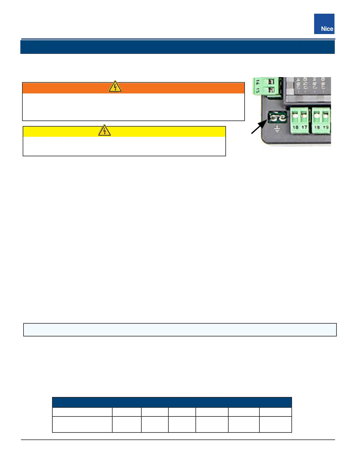
Connect ground wire to the grounding lug on the lower left corner of the 1050 control board (FIGURE 4-1).
Alternatively, bonding of the control box can be done by drilling a hole in the control box, removing the powder
coating around the hole, and bonding the copper ground wire to that area with a bolt.
TABLE 12-1: MAXIMUM RUN PER WIRE GAUGE
110V/AWG GAUGE 14 12 10 8 6 4
MAX RUN
180 FT
(54.8m)
280 FT
(85.3m)
460 FT
(140m)
700 FT
(213.3m)
1150 FT
(350.5m)
1800 FT
(548.6m)
Use Table below to determine high voltage wire size requirements. Distance shown in the chart is measured
from the operator to the power source. If power wiring is greater than the maximum distance shown, a service
feeder is recommended. When large gauge wire is used, a separate junction box must be installed for the
operator connection.
Wire table is based on stranded copper wire. Wire run calculations are based on a 110 VAC power source with
a 3% voltage drop on the power line, plus an additional 10% reduction in distance to allow for other electrical
losses in the system.
SECTION 4: 120VAC ELECTRICAL WIRING SAFETY
GROUND LOCATION
GROUND
LUG
DANGER!
’ To reduce risk of severe injury and death follow all safety procedures!
’ Do not wire AC mains power to metal control box without earth ground
connection!
CAUTION
Do not wire ac power to the control board! The control board
operates on 12VDC or 24VDC only!