CBOX1050
Installation and Programming Manual
5454
support.hysecurity.com
7
8
9
10
11
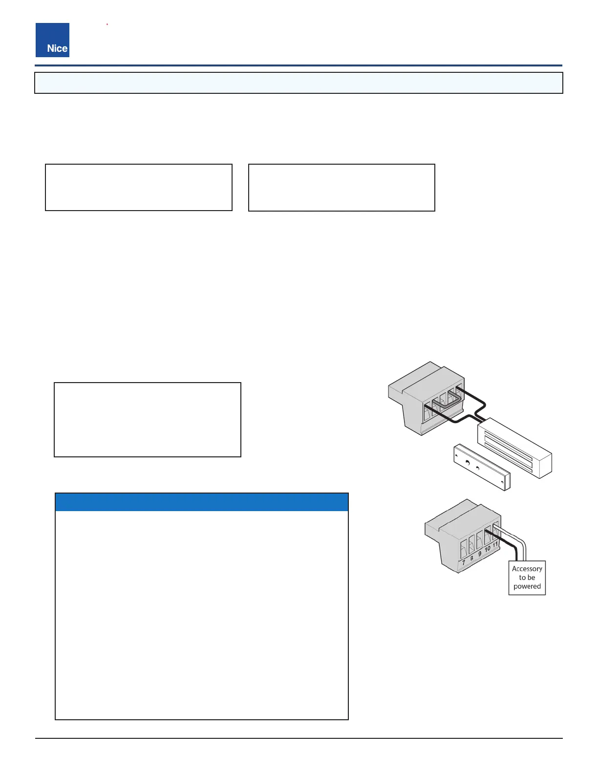
MAGNETIC LOCK
WIRING (EXAMPLE)
OUT 1 OUT 2
PIN 7 = N.C. (Normally Closed)
PIN 8 = Com (Common)
PIN 9 = N.O. (Normally Open)
PIN 10 = GND (Ground)
PIN 11 = V+
* POWER OUT
PIN 1 = N.C. (Normally Closed)
PIN 2 = Com (Common)
PIN 3 = N.O. (Normally Open)
PIN 4 = N.C. (Normally Closed)
PIN 5 = Com (Common)
PIN 6 = N.O. (Normally Open)
OUT 1 / OUT 2 (1-6):
Individual, isolated relays provide dry contacts for switching accessories based on programming of the “Auxiliary
IO” function. These outputs are programmed in the “FUNCTION / Auxiliary I/O” menu.
MAGNETIC LOCK (7-11):
• Provides fused power (1.85A max) and isolated relay dry contacts for electrically powered and maintained
magnetic locks.
• This connection is used to install the magnetic lock. Consult lock manual for specifics on installation and
wiring.
• The output time for magnetic lock activation/deactivation may be adjusted from 0 to 5 seconds.
• When the control board is in standby mode, power is still present at terminals 10 and 11. If standby mode is
used (especially in a solar application) and a magnetic lock is not used, terminals 10 and 11 may be used to
provide power to other accessories.
AUX. POWER OUT
WIRING (EXAMPLE)
9.1 OUTPUT CONNECTORS
*NOTICE
The output voltage of terminal 11 is the same as the highest
incoming voltage (on battery OR Main DC Power) to the
control board.
EXAMPLES:
’ If you are using a 12VDC battery to power the control
board connected to the Battery input, and the voltage of
the battery is 13.5VDC - terminal 11 will have a 13.5VDC
output.
’ If you are using a power supply input of 32VDC to the
control board connected to the Main DC Power input -
terminal 11 will have a 32VDC output.
’ If you are using a power supply connected to Main DC
Power (at 32VDC) and also using a battery connected to
the Battery input (at 13.5VDC) - terminal 11 will have an
output of 32VDC.