ENGLISH – 31
TERMINAL LEDS ON THE CONTROL UNIT
Status Meaning Possible solution
CLOSE LED
OFF
Everything normal CLOSE input not active.
On
Intervention of the CLOSE input This is normal if the device connected to the CLOSE input is actually active.
HP SbS LED
OFF
Everything normal Hp SbS input not active.
On
Intervention of the HP SbS input Normal if the device connected to the HP SbS input is active.
FC1 limit switch LED
OFF
Intervention of the limit switch
With “RH” right-hand installation: the boom is in the closed position.
With “LH” left-hand installation: the boom is in the open position.
On
No intervention of the limit switch
With “RH” right-hand installation: the boom is in a position other that the
closed position.
With “LH” left-hand installation: the boom is in a position other that the open
position.
FC2 limit switch LED
OFF
Intervention of the limit switch
With “RH” right-hand installation: the boom is in the open position.
With “LH” left-hand installation: the boom is in the closed position.
On
No intervention of the limit switch
With “RH” right-hand installation: the boom is in a position other that the open
position.
With “LH” left-hand installation: the boom is in a position other that the closed
position.
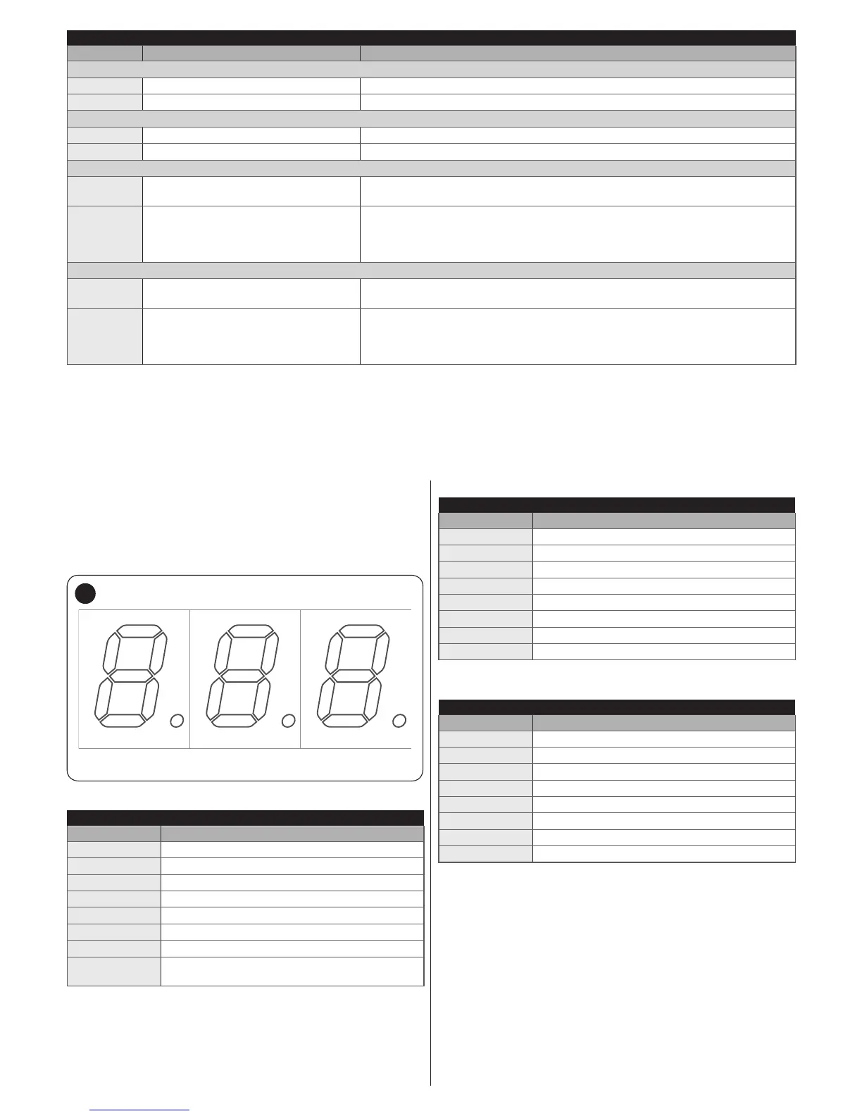
8.3.1 Display diagnostics
Selecting with the encoder the “din” diagnostics mode and
conrming the choice, the display will show with its 3 digits the
status of the inputs (Table 10, Table 11 and Table 12); each lit
segment of the display signals that the corresponding input is
active.
F3
E3
B3
C3
dp3
G3
D3
45
Table 10
DISPLAY DIAGNOSTICS
Segment Input
A1
Loop 1
B1
Close
C1
HP SbS
D1
Loop 2
E1
Open
F1
Sbs
G1
Free
dp1
one ash each second, signals the operation of
the board
Table 11
DISPLAY DIAGNOSTICS
Segment Input
A2
FC1 OPEN limit switch
B2
Close button
C2
RH direction selector
D2
Battery-powered operation
E2
LH direction selector
F2
Open button
G2
FC2 CLOSE limit switch
dp2 Encoder A input [Note 1]
Table 12
DISPLAY DIAGNOSTICS
Segment Input
A3
FA1 opening photocell
B3
ON when PHOTO is active
C3
ON when PHOTO II is active
D3
FA2 opening photocell
E3
ON when PHOTO 1 is active
F3
ON when PHOTO 1 II is active
G3
ON Master control unit has acquired the slave
dp3 Encoder B input [Note 1]
Note 1 The LEDs can be switched on or off, depending on the
position of the magnet when the motor stops; the LEDs
ash when the motor moves