3 – English
EN
USE LIMITATIONS
2
q3GD,"BNMSQNKTMHSB@MADTRDCDWBKTRHUDKXVHSG@M@RXMBGQNMNTRRHMFKDOG@RDLNSNQ3GDLNSNQLTRSADa) powered from the mains
and sized for the same voltage that powers the control unit; b) equipped with a thermal cut-off; c) equipped with a mechanical device that limits
its movement (limit switch); d)DPTHOODCVHSGBNMMDBSHNMRSNBNMCTBSNQRf"NLLNMtf.ODMt@MCf"KNRDt
• The radio receiver incorporated in the control unit is only compatible with transmitters that adopt the FLOR, O-CODE or SMILO radio coding
protocols (these are Nice standards).
q%TQSGDQTRDKHLHS@SHNMR@QDRODBHjDCHMSGDf/QNCTBSSDBGMHB@KRODBHjB@SHNMRtBG@OSDQ
INSTALLATION
3
Important! - Prior to installing the product, check its use limitations by reading Chapters 2 and 7.
Check that the temperature is suitable for the type of application.
The product must not be installed outdoors.
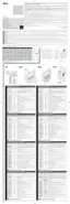
When drilling the control unit box for passing the cables (Fig. 1-C), it is important to remember that the cables must always
enter the box from below. Moreover, take suitable precautions to guarantee the required protection rating (IP 44) for the type of
installation.
Before proceeding with the installation, prepare the electrical cables required for the system by referring to Fig. 2b and to “Table
7HFKQLFDOVSHFLƄFDWLRQVRIHOHFWULFDOFDEOHVr
Warning! – When laying the tubes for protecting the electrical cables and when laying the cables into the control unit housing,
bear in mind that due to possible water deposits in the junction wells, the cable protection tubes might create water vapour the
control unit, with consequent damage to the electronic circuits.
Install the control unit by referring to Fig. 1.