6
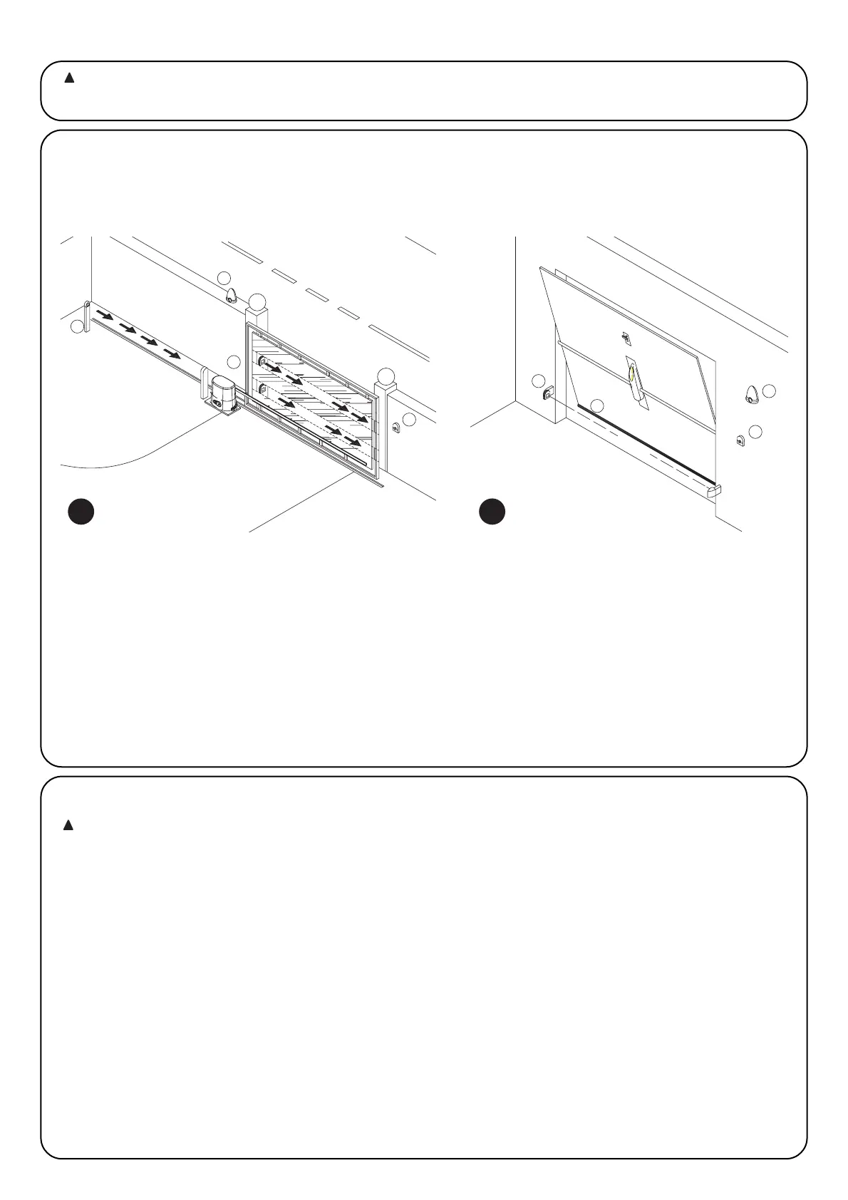
2.1) Typical system layout
In order to explain certain terms and aspects of an automatic door or gate system, we will now illustrate a typical system layout.
ROBO / THOR OTTO
1) Pair of ““Photo” photocells
2) Flashing lamp
3) Keylock selector
4) Pneumatic edge
5) Pair of “Photo 2” photocells
In particular, please note that:
• All the photocells produced by NICE feature the synchronism system which eliminates the problem of interference between
two pairs of photocells (please consult the photocell instructions for further details).
• The ““Photo” pair of photocells have no effect during opening while they invert movement during closing.
• The ““Photo2” pair of photocells have no effect during closing while they invert movement during opening.
Automatic gate and door systems may only be installed by
qualified fitters in the full respect of the law. Comply with the
warnings shown in the “Warnings for fitters” file.
2.2) Electrical connections
To safeguard the operator and avoid damaging the
components while you are wiring or plugging in the
various cards: under no circumstances may the unit be
electrically powered.
• Power the unit using a 3 x 1.5 mm
2
cable: should the distance
between the unit and the earth connection exceed 30m, install
an earth plate near the unit.
• Use wires with a minimum cross-section of 0.25mm
2
to connect
low voltage safety circuits.
• Use shielded wires if the length exceeds 30m and only connect
the earth braid to the control unit side.
• Do not make connections to cables in buried boxes even if they
are completely watertight.
• If the inputs of the Normally Closed (NC) contacts are not used
they should be jumped with the “24V common” terminal except
for the photocell inputs if the phototest function is enabled, for
further information please see the “Phototest” paragraph.
• If there is more than one (NC) contact on the same input, they
must be connected in SERIES.
• If the inputs of the Normally Open (NA) contacts are not used
they should be left free.
• If there is more than one (NA) contact on the same input, they
must be connected in Parallel.
• The contacts must be mechanical and potential-free; no stage
connections are allowed, such as those defined as "PNP",
"NPN", "Open Collector", etc..