GB
3
The control unit for the SP6000 is suitable for moving sectional doors,
up-and-over doors with counterweights and up-and-over doors with
springs; these are controlled by electromechanical actuators
powered by 24 Vdc motors.
The board uses a system for controlling the force developed by the
motor; this is done by measuring the amount of current absorbed.
This system recognises obstacles during normal movement (anti-
crush safety feature). The level of current sensitivity can be set during
the programming phase. To make it easier to recognise the various
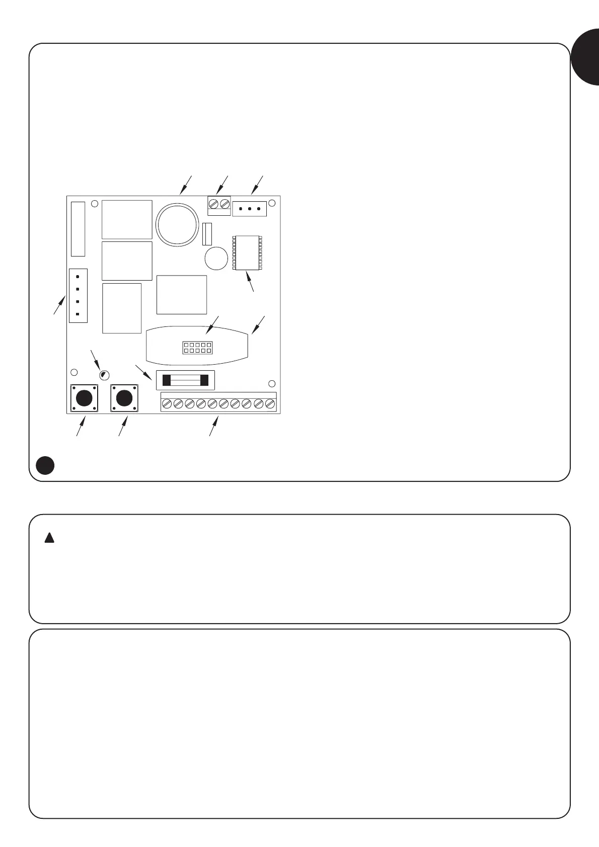
parts of the control unit, Fig. 1a shows the main components.
1) Product description:
2.1) Preliminary checks
Before starting installation make sure that all the material is suitable
for installation and complies with legal requirements. As well as
checking all the points shown in the “Warnings for fitters”, this section
also contains a specific check list for the SP6000 gear motor.
• Check the strength and mechanical consistency of the door and
make sure safety margins and minimum distances are respected.
• The power line must be protected by an overload cut-out switch
and a residual current circuit breaker.
• Power the control unit using the plug provided with the product.
Any extension cables used should be 3 x 1.5 mm
2
.
• Use wires with a minimum cross section of 0.25 mm
2
to connect
low voltage safety circuits.
Use shielded wires if the length exceeds 30 m and connect the
earth braid at the control unit end only.
2) Installation:
Automatic gate and door systems may only be installed
by qualified fitters in the full respect of the law. Comply
with the warnings shown in the “Warnings for fitters”
chapter.
Description
A Closing manoeuvre relay (CLOSE)
B Opening manoeuvre relay (OPEN)
C Speed change relay (FAST)
D Transformer connector
E OK Led
F Programming button (PROG)
G Step-by-step button (PP)
H Low voltage rapid fuse (2A)
I Input and output connection terminal board
L Radio receiver box
M Radio receiver connector
N Flashing lamp/Photo-test output relay
O Microcontroller
P Travel stop connector
Q Motor connection terminal board
R Courtesy light

 Loading...


