4
2.3) Electrical connections
To protect the fitter and avoid damaging the
components while electrical connections are being made
or the radio receiver is being connected, under no
circumstances may the unit be electrically powered.
• If the inputs of the NC (Normally Closed) contacts are not used
they should be jumped with the “24V Common” terminal (except
for the photocell inputs; for information please see the “Photo-test”
function).
• If there is more than one NC contact, they must be connected in
“series”.
• If the inputs of the NO (Normally Open) contacts are not used they
should be left free.
• If there is more than one NO contact, they must be connected in
“Parallel”.
• The contacts must be mechanical and potential-free; no stage
connections are allowed, such as those defined as "PNP", "NPN",
"Open Collector", etc..
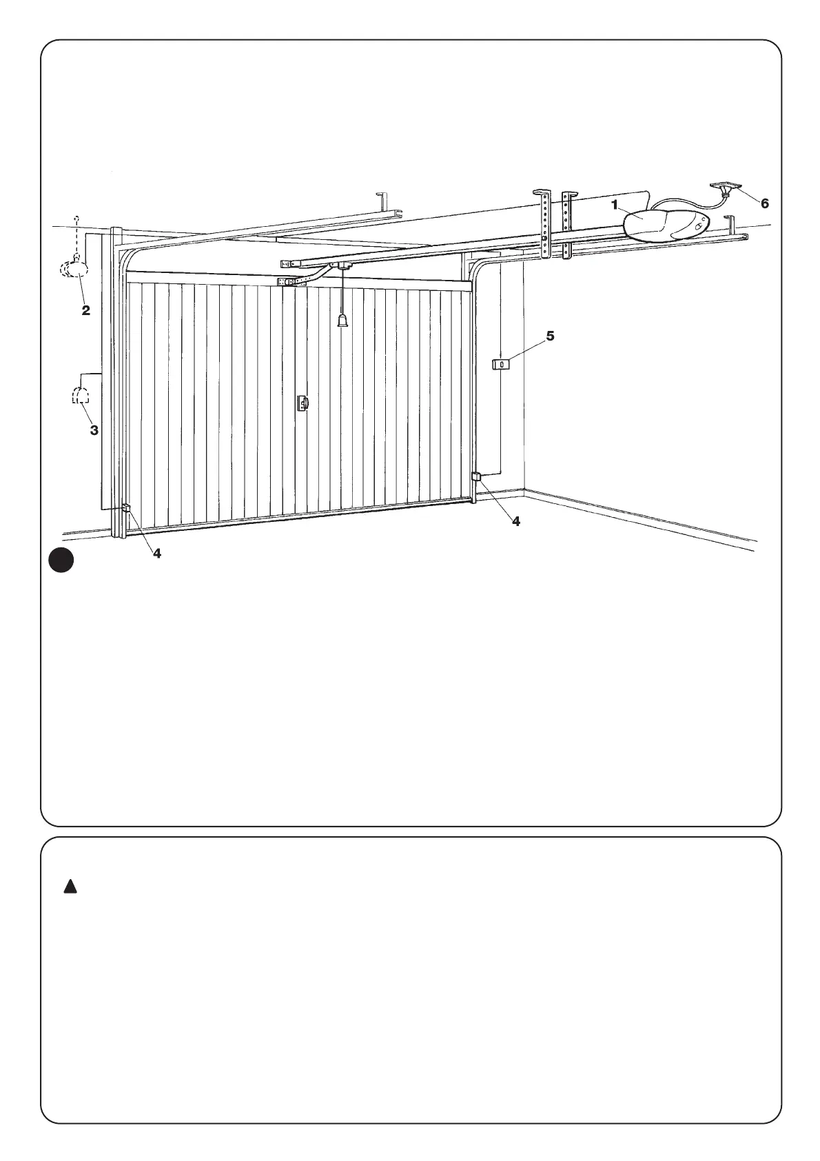
2.2) Typical system layout
To clarify certain terms and aspects of a door automation system, we
have included a typical example of a system for an up-and-over door.
Description
The description refers to the typical system shown in Fig. 2
1. SP6000.
2. Flashing light with built-in aerial (installed outdoors).
3. Key or keypad switch (installed outdoors) to connect to the
“Step-by-step” input.
4. Two photocells to connect to the “Photo” input.
5.
Control buttons to connect to the “Step-by-step” or “Stop” input.
6. Power supply plug.
2

 Loading...


