15
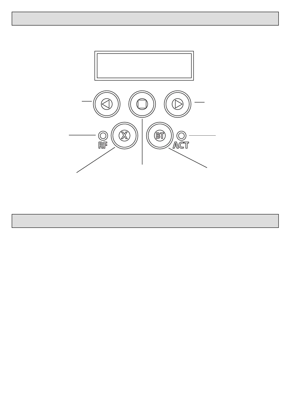
Using the control card display and dashboard.
The control unit is equipped with a LCD display and interacve keys for simplied programming and diagnoscs. All setup, of the various features,
requires that the control card dashboard be used. Below are the funcons of each key on the dashboard.
ACT
RF
Navigate backward in menus, decrease
values, indicate lehand closing barrier
in runme setup funcon or enter
diagnoscs menu while in standby.
Exit menu levels without saving.
Radio acvity indicator. Processor acvity indicator.
Navigate forward in menus, increase
values, indicate righthand closing
barrier in runme setup funcon or
enter diagnoscs menu while in standby.
Test BT mode when in standby or exit
all the way back to standby without
saving when in programming.
Enter programming, advance to next
level of opon on display, save value
on display.
Control card programming and setup.
1. Runme setup. - Page 18.
2. Collision force sensing. Safety level setup. - Page 19.
3. Safety beam setup. - Page 19.
4. BT triggers operang mode selecon and setup. - Page 20.
5. Receiver setup.
a. Learn remotes. - Pages 22, 23 and 24.
b. Erase remotes. - Pages 25 and 26.
c. Diagnose remotes. - Page 27.
d. Receiver informaon. - Page 28.
6. Advanced menu. - Pages 29 and 30.
a. Barrier speed
b. So stop speed.
c. Auxiliary relay setup.
d. Blue-bus setup.
e. Power sengs.
f. Controller setup.
g. Controller informaon.
h. IEC Standards mode. Enable/disable. (Safety beams must be installed and congured before you can enable this mode)
i. Reset and restore.
Programming menu quick reference guide:
 Loading...