11
Rev. 2 – 10
th
November2015
To set the speed through the Modbus protocol is necessary to set a dedicated register
(Input Type – HOLDING REGISTER 34 see “ Modbus communication” paragraph )
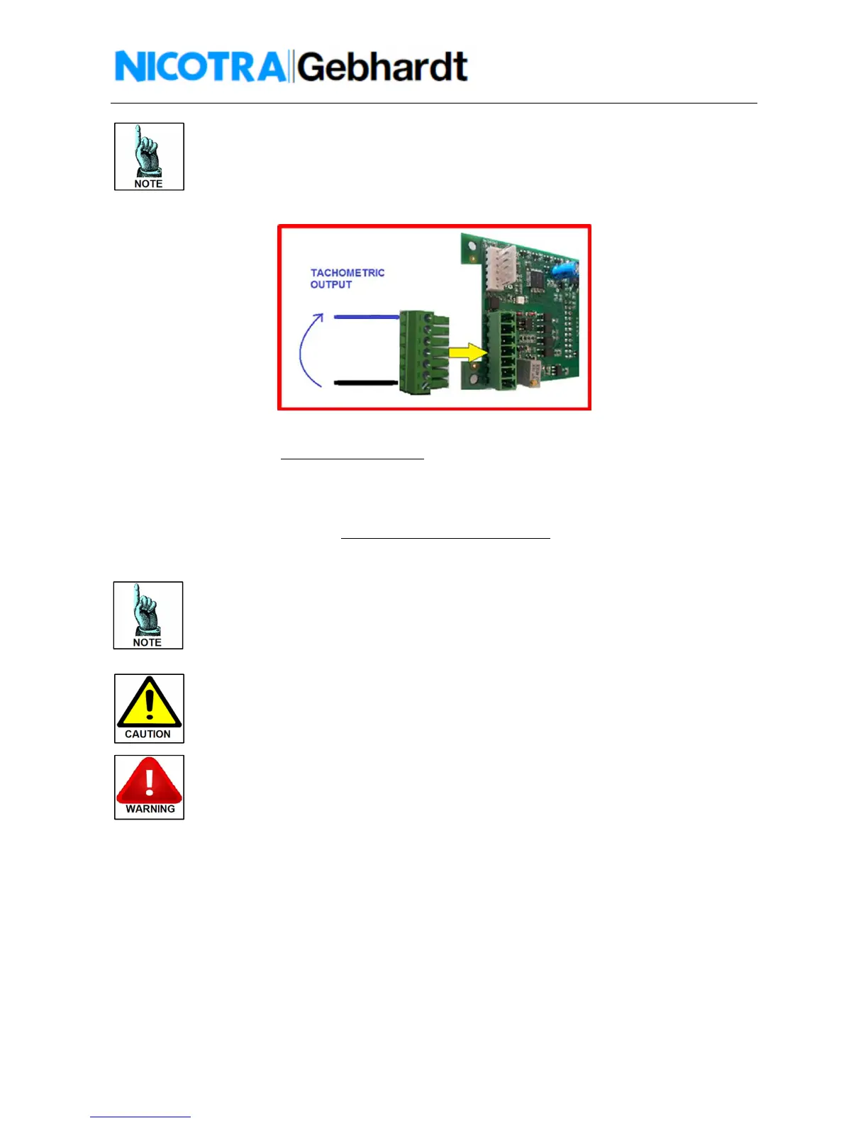
In figure 13 is shown how to connect the tachometric output.
Fig.13 – Driver – CONTROL BOARD tachometric output connection
The tachometric output is a 0 to 5V PWM waveform at 1KHz with the following duty cycle:
!
"#$
!
%
Remember that the Speed
Real
= 0 below Speed
min
The +10V power supply available of the Driver is intended to be used with a
potentiometer of minimum 2KOhm.
Any different devices connected to it could bring to an undesired functioning of the Driver
or the connected device. The absorbed current must be <5mA.
Don’t reverse the input signal or connect the +10V to signal ground.
The Driver could be damaged.
Don’t apply signals with voltage higher than 10V
The Driver could be damaged.
 Loading...