25
Rev. 2 – 10
th
November2015
REDUCING THE MAX CURRENT
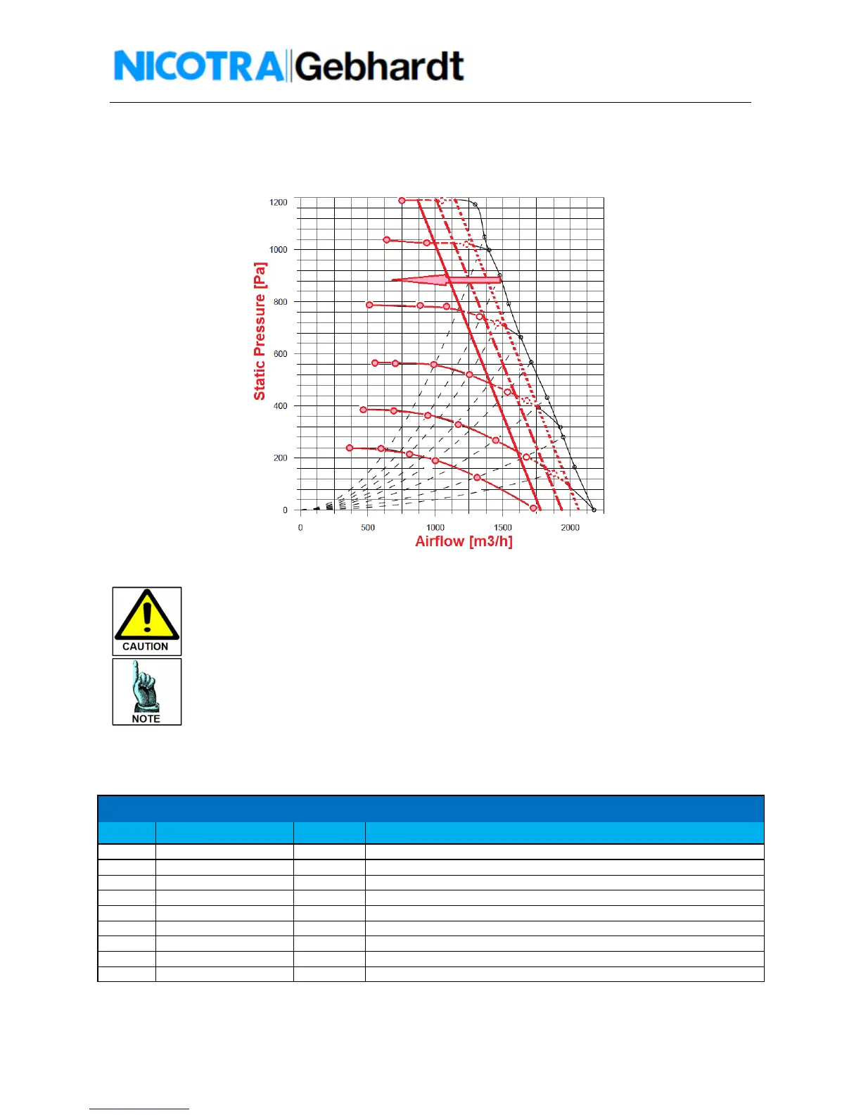
In figure 29 is shown the behavior of the fan by reducing the MAX CURRENT through the modification of
the register number 7 into the Modbus Holding Register
Fig.29 – DDMP Reducing the MAX CURRENT limits – Example DDMP 7/7 Tight
The MAX CURENT can be decreased down to 2000mA for 1KW Driver and 5500mA for
2KW Driver. Lower values can affect the starting phase of the fan.
The MAX POWER can be decreased down to 10% of the max achievable power of the
driver.
The fan speed can’t be lower than 400rpm for 1KW driver fan sizes and 200rpm for 2KW
fan sizes.
Input Register
In the table 4 are indicated the most significant Modbus input registers.
Name units Description
0 Driver Version Adim Indicates the version of the driver.
2 SPEED REFERENCE rpm Indicates the target speed set through the potentiometer or Modbus.
3 MEASURED SPEED rpm Indicates the real speed of the fan.
10 ALARM - 1 See table 4 Indicates the functioning status of the Driver.
12 MOTOR CURRENT mA Indicates the absorbed current by the motor
14 POTENTIOMETER INPUT Volts/10 Indicates the potentiometer voltage value
15 TEMPERATURE Celsius Indicates the Driver power module temperature
17 ALARM - 2 See table 4 Indicates the functioning status of the Driver.
31 ABSORBED POWER W Indicates the Driver absorbed Power.
Table 4 – Holding Register
 Loading...