10
Rev. 2 – 10
th
November2015
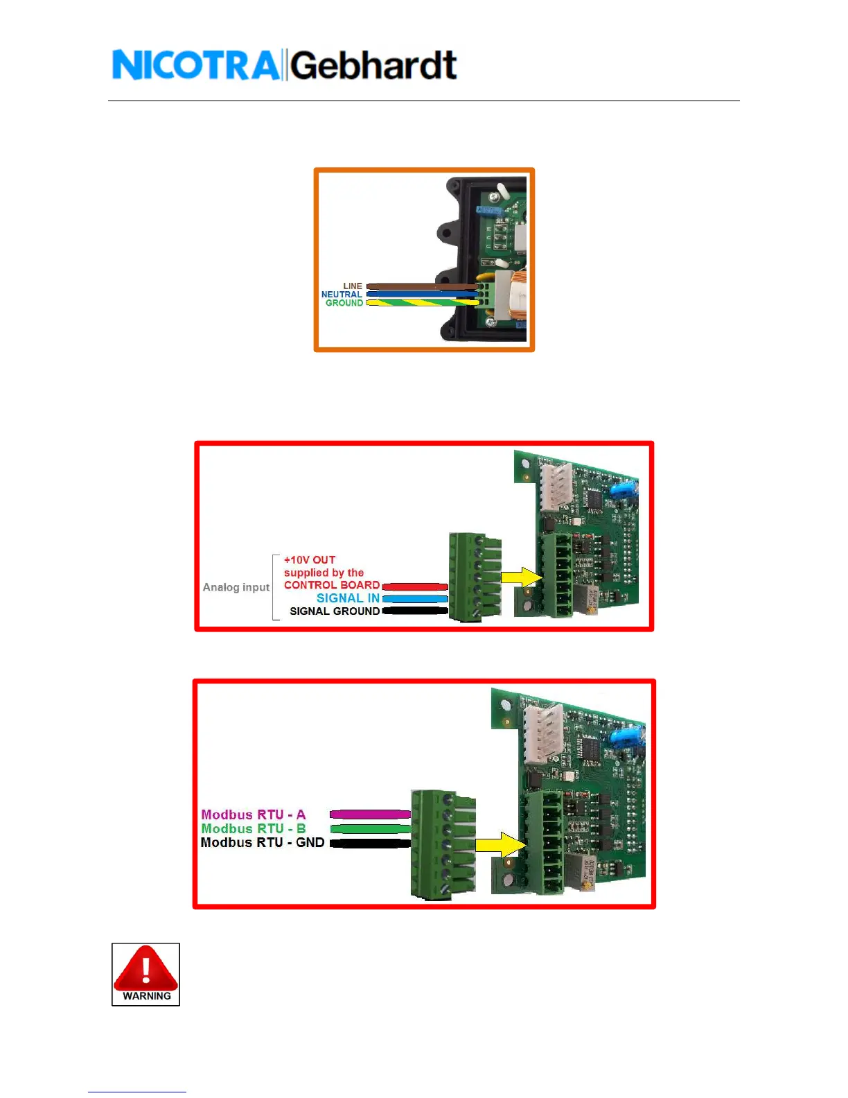
Power supply connection:
Single Phase 230V (tolerance ± 10%) frequency 50/60Hz (Fig. 10)
Fig. 10 – Driver – POWER SUPPLY connection
Control Board connection:
As default the Driver is programmed for an analog input command of 0-10V (Fig. 11).
The analog input can accept also a PWM signal with f>1kHz.
Fig. 11 – Driver – CONTROL BOARD analog connection
In figure 12 is shown the Modbus connection diagram.
Fig.12 – Driver – CONTROL BOARD modbus connection
Don’t use devices having the signal GND connected to the NEUTRAL cable of the power
supply. The driver may be damaged or not functioning properly.
 Loading...