Commander C200/C300 Step By Step Guide 7
Issue Number: 2
English
Français Deutsch Italiano Español
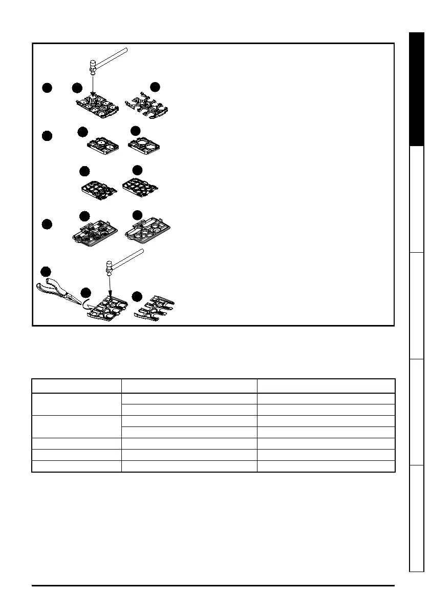
Removing the finger-guard break-outs
STEP 6: Wire the drive up
When wiring the drive the power, ground and control connections, they should be tightened to the recommended
torque settings shown in the table below:
Table 6-1 Recommended torque settings
Model size Terminal description Torque settings
All
Control terminals 0.2 N m (0.15 lb ft)
Relay terminals 0.5 N m (0.37 lb ft)
5
Power terminals 1.5 N m (1.1 lb ft)
Ground terminals 2.0 N m (1.4 lb ft)
6 Power and ground terminals 6.0 N m (4.4 lb ft)
7 Power and ground terminals 12 N m (8.85 lb ft)
8 and 9 Power and ground terminals 15 N m (11.1 lb ft)
A: Size 5 to 9
B: Size 5 only
C: Size 6 only
D: Size 7 to 9
Place finger-guard on a flat solid surface and hit relevant
break-outs with hammer as shown (1). For sizes 7 to 9 pliers
can be used to remove the break-outs, grasp the relevant
break-out with the pliers and twist it as shown (3).
Continue until all required break-outs are removed (2).
Remove any flash / sharp edges once the break-outs
are removed.
Finger guard grommets are supplied in the kitbox for size 5
and 6.