Do you have a question about the Nidec Commander C300 and is the answer not in the manual?
Explains the structure of the drive model number.
Defines the nomenclature for drive model numbers.
Lists harmonized standards for drive systems.
Explains the structure of the drive model number.
Defines the nomenclature for drive model numbers.
Lists harmonized standards for drive systems.
Explains the structure of the drive model number.
Defines the nomenclature for drive model numbers.
Lists harmonized standards used for compliance.
Explains the structure of the drive model number.
Defines the nomenclature for drive model numbers.
Lists harmonized standards for drive systems.
Explains warning, caution, and note symbols used in the manual.
Details safety hazards and installer competence requirements.
Outlines installer responsibility for correct equipment installation and safety.
Highlights installer's duty to comply with all relevant safety and EMC regulations.
Introduces the drive models covered by the guide and scope.
Details the structure and components of the drive model number.
Recommends AC supply fuse protection against overload/short-circuits to prevent fire.
Provides data on 200V drive ratings, cable sizes, and fuse ratings.
Provides data on 400V drive ratings, cable sizes, and fuse ratings.
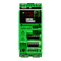
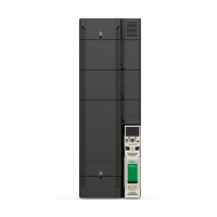
Illustrates key features and connection points of the drive.
Provides a key to identify drive features and connection points.
Lists the components included with the drive package for different sizes.
General safety warnings for mechanical and electrical installation.
Warns about stored lethal voltage in capacitors after power disconnection.
Stresses that installation must be by qualified professionals familiar with safety/EMC.
Specifies enclosure requirements for preventing contamination and ensuring safety.
Details environmental factors to protect the drive from (moisture, dust, etc.).
Discusses enclosure requirements for fire protection and US/non-USA recommendations.
Stresses the need for an isolation device before servicing or removing covers.
Warns about stored lethal voltage in capacitors after power disconnection.
Warns about high heatsink temperatures and safe lifting of heavy drives.
Illustrates drive dimensions for various sizes.
Shows dimensions and hole locations for surface mounting.
Illustrates dimensions and hole locations for through-panel mounting.
Lists surface and through-panel mounting kits, quantities, and part numbers.
Specifies required spacing between drives for proper cooling.
Diagrams enclosure layout with clearances and component placement for sizes 7-8.
Diagrams enclosure layout with clearances and component placement for sizes 9-10.
Illustrates the correct installation of the main gasket for environmental sealing.
Lists optional external EMC filters with corresponding CT part numbers.
Details specifications for optional external EMC filters, including current, voltage, and dissipation.
Provides dimensions and weight for optional external EMC filters.
Lists dimensions for size 7 external EMC filters.
Lists dimensions for size 8 external EMC filters.
Lists dimensions for size 9A external EMC filters.
Lists dimensions for sizes 9E/10E external EMC filters.
Provides torque settings for drive control terminal connections.
Specifies recommended and maximum terminal torque for power connections.
Warns about lethal voltages in various drive locations and terminals.
Stresses the need for an isolation device before servicing or removing covers.
Warns about lethal voltage in capacitors after power disconnection.
Diagrams power and ground connections for drives size 7 and 8.
Specifies protective ground cable size requirements based on conductor size.
Provides special attention notes for ungrounded IT supplies and EMC filters.
Advises on selecting appropriate motor cables and ensuring correct parameter settings.
Explains suitable RCD types (Type B) for three-phase inverter drives.
Warns about high leakage current when EMC filters are used, requiring fixed ground connections.
Details grounding arrangements for EMC, including back-plate and cable connections.
Illustrates proper grounding of drive, motor cable shields, and filters.
Provides guidelines for situations requiring interruption of motor cables.
Details how to bond motor cable shields to the back-plate when using terminal blocks.
Provides continuous current ratings for Normal and Heavy Duty at 200V and 400V.
Provides typical input current values for power flow and loss calculations.
Lists maximum continuous input current values for cable/fuse selection.
Details input current and fuse ratings for 200V drives.
Provides torque settings for drive control terminal connections.
Specifies recommended and maximum terminal torque for power connections.
Summarizes immunity performance against various electrical disturbances.
Shows emission compliance levels for Size 7, 200V drives.
Details emission compliance for Size 7, 400V drives.
Provides emission compliance for Size 7, 575/690V drives.
Lists emission compliance for Size 8, 200V drives.
Lists optional external EMC filters with corresponding CT part numbers.
Details specifications for optional external EMC filters.
Provides UL file references for the drives and Safe Torque Off function.
Discusses enclosure ratings like Open Type, Type 1, Plenum, and Through-hole mounting.
States drives are evaluated for Overvoltage Category III.
Discusses suitability for circuits with up to 100,000 RMS symmetrical amperes.
Emphasizes tightening terminals to the specified rated torque.
States UL Listed connectors should be used for ground connections.
Mandates branch circuit protection per NEC, Canadian Electrical Code, and local codes.
Explains regenerative operation and AC supply voltage limits.


