Safety information Product information Mechanical installation Electrical installation Multi axis system design Technical data
Digitax HD M75X Series Installation and Technical Guide 81
Issue Number: 5
Common to all Feedback types
Sincos encoder resolution
The sine wave frequency can be up to 500 kHz but the resolution is
reduced at high frequency. Table 4-21 shows the number of bits of
interpolated information at different frequencies and with different
voltage levels at the drive encoder port. The total resolution in bits per
revolution is the ELPR plus the number of bits of interpolated
information. Although it is possible to obtain 11 bits of interpolation
information, the nominal design value is 10 bits.
Table 4-21 Feedback resolution based on frequency and voltage level
4.13 Communication connections
The Digitax HD M753 drive offers EtherCAT fieldbus communications
and the Digitax HD M751 drive offers a 2 wire EIA 485 interface. This
enables the drive set-up, operation and monitoring to be carried out with
a PC (Connect) or controller if required.
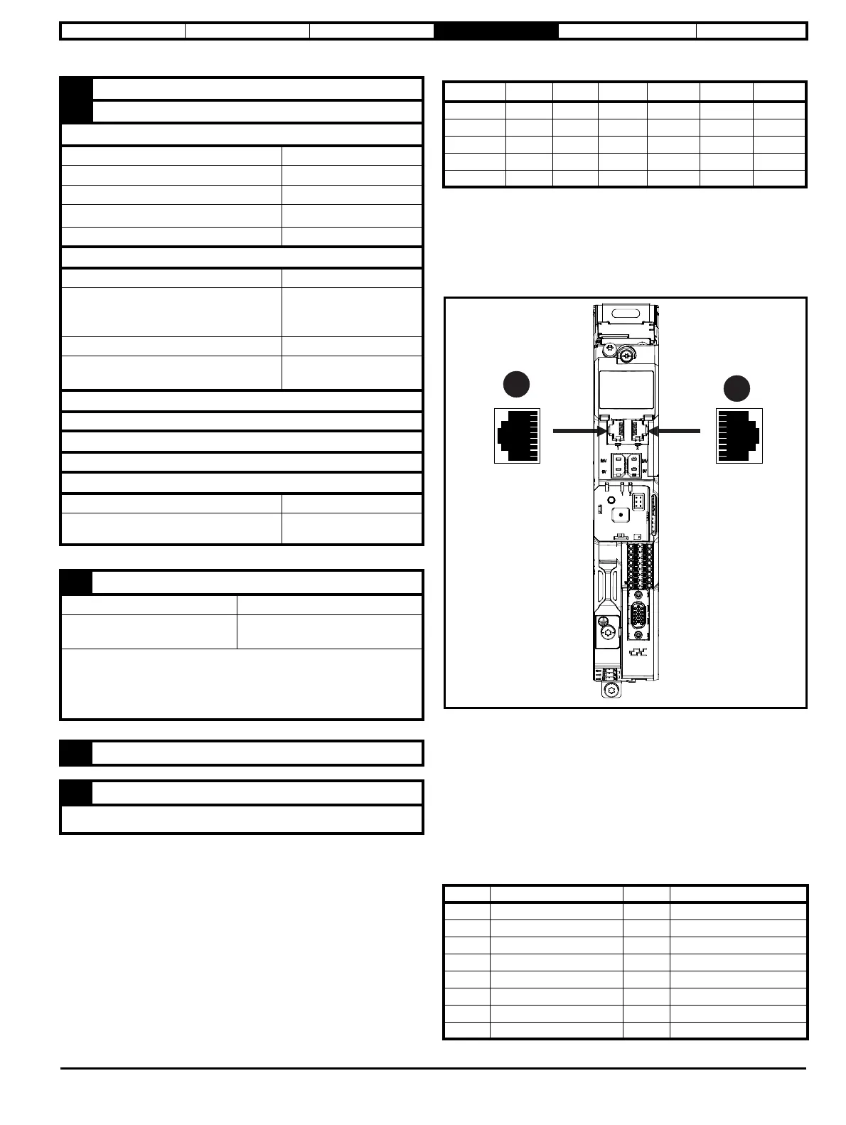
Figure 4-29 Location of the communication connectors
4.13.1 Digitax HD M753 EtherCAT fieldbus
communications
The Digitax HD M753 has two RJ45 Ethernet ports for the EtherCAT
network, refer to Figure 4-29 Location of the communication connectors.
A: EtherCAT port 1.
B: EtherCAT port 2.
Cables should be shielded and as a minimum, meet TIA Cat 5e
requirements.
The shell of the RJ45 connector is capacitively coupled to ground.
Table 4-22 EtherCAT terminal descriptions
11
W, Clock, Not used, Not used
12
W\, Clock\, Not used, Not used
AB Servo (3), FD Servo(4), FR Servo (5
), SC Servo (12)
Type EIA 485 differential receivers
Maximum input frequency 512 kHz
Line loading 1 unit load
Line termination components
120
(switchable)
Working common mode range –7 V to +12 V
SC EnDat (9), SC SSI (11)
Type Differential voltage
Maximum Signal level
1.25 V peak to peak (sin with
regard to sinref and cos with
regard to cosref)
Maximum input frequency See Table 4-21
Maximum applied differential voltage and
common mode voltage range
4 V
EnDat (8), SSI (10), BiSS (13)
Not used
Resolver (14)
Not used
Common to All
Absolute maximum applied voltage relative to 0V -9 V to 14 V
Maximum differential voltage between terminals
(with termination resistors enabled)
6 V
13
Feedback device supply
Supply voltage 5.15 V ±2 %, 8 V ± 5 % or 15 V ± 5 %
Maximum output current
300 mA for 5 V and 8 V
200 mA for 15 V
The voltage on Terminal 13 is controlled by Pr 03.036. The default for this
parameter is 5 V (0) but this can be set to 8 V (1) or 15 V (2). Setting the encoder
voltage too high for the encoder could result in damage to the feedback device.
The termination resistors should be disabled if the outputs from the encoder are
higher than 5 V.
14
0V Common
15
Motor thermistor input
Thermistor type is selected in P1 Thermistor Type (03.118).
Volt/Freq 1 kHz 5 kHz 50 kHz 100 kHz 200 kHz 500 kHz
1.2 11 11 10 10 9 8
1.0111110997
0.8101010987
0.610109987
0.4999876
Pin EtherCAT port 1 - IN Pin EtherCAT port 2 - OUT
1 Transmit + 1 Transmit +
2 Transmit - 2 Transmit -
3 Receive + 3 Receive +
4 Not used 4 Not used
5 Not used 5 Not used
6 Receive - 6 Receive -
7 Not used 7 Not used
8 Not used 8 Not used
 Loading...


