Electric Power Generation
Installation and maintenance
LSA 52.3 / LSA 53.2 / LSA 54.2
Industrial Range Alternators
__________________________________________________________________________________________________
5
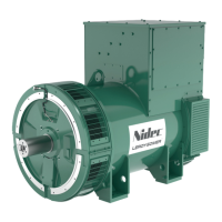
1.1.2.4 Object projection risk
DANGER:
IN THE EVENT OF A MAJOR ACCIDENT, DEBRIS CAN
BE EJECTED FROM THE MACHINE THROUGH THE
AIR INLET OR OUTLET OPENINGS. THESE DEBRIS
CAN CAUSE A FATAL ACCIDENT. DO NOT ENTER
HAZARDOUS AREAS DURING MACHINE OPERATION.
NOTE:
This risk must be considered in the risk analysis of the
site concerned.
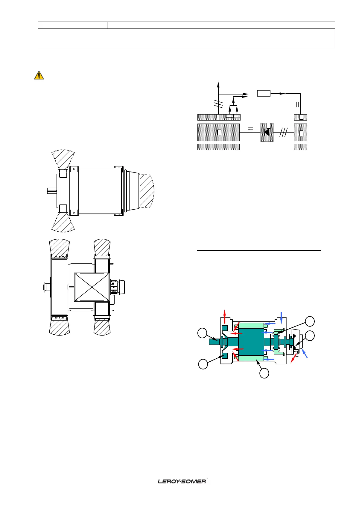
1.2 GENERAL DESCRIPTION
1.2.1 Generator (arep)
The synchronous generator is an alternating-current
machine, without ring or brush. The machine is cooled by
the flow of air through the machine.
Use the drawings of chapter 10 in order to better
understand the machine.
The Automatic Voltage Regulator (item 6) supplies the
inductor exciter field (static part; item 1) with DC current.
The Exciter (item "1" & "2”) works as an inverse alternator.
The Exciter armature (rotating part; item 2) generates a
three-phase current which supplies the rotating diode
bridge (rotating part; item 3).
The Rotating diode bridge (rotating part; item 3) rectifies
the three-phase current into DC current which supplies the
Pole wheel (rotating part; item 4).
The pole wheel (rotating part; item 4) excites the alternator
armature (static part; item 5) which generates a three-
phase current.
1- Excitation field winding
2- Excitation armature
3- Rotating diodes bridge
4- Revolving field
5- Alternator armature
6- Automatic Voltage Regulator
H1- AREP winding harmonic detection 1
H3- AREP winding harmonic detection 3
1.2.2 Excitation system
The excitation system is mounted at the rear of the
machine.
2. DESCRIPTION OF SUB-ASSEMBLIES
2.1 - STATOR
2.1.1 Stator of the electric machine
The alternator stator is a stack of low loss steel magnetic
laminations assembled under pressure. The stator coils are
inserted and blocked in the slots, then impregnated with
varnish and polymerised (VPI system).
1 - Stator
2 - Rotor
3 - Exciter
4 - Rotating diodes
5 - Fan
a - Stator Air inlet (cold air)