ALIGNMENT
ALIGNMENT PRECAUTIONS
1, As
the ALPHA 220
is a power amp I ifier with large
output power
, it consumes much electrical power and
a great amount of current flows in the
power source
line of the primary
side. Therefore, in the case when
it is connected to the source by an
extension cord
the size of the extension cord should be equal or
larger than that of the power source cord of the
ALPHA 220. Otherwise
, the voltage might be reduced
or the extension cord might
generate excessive heat
because of the resistance which the cord has
, then
not only can proper alignment be done
, but also it is
very dangerous.
If the power sources are supplied to the ALPHA 220
and the instruments by branching off from one cord
the voltage is sometimes dropped down and the
stability of the instruments goes down.
The ALPHA 220 and the
instruments should be con-
nected to the power
sources by using independent
cords. The ALPHA 220 must take the power source
from AC outlet of the wall side,
As there are many parts which hold
high voltages in
the circuit and the parts inside of the ALPHA 220
, be
careful not to receive an
electric shock. I
n the case
of connecting and
taking off the instruments
, you
must turn off the power
switch of the ALPHA 220
before getting on the work.
4. When
the circuit happens to be shorted by the
drivers
or test probes used for alignment through mistake
the circuit and the parts will be
damaged. As the
damage is larger than that of
ordinary amplifiers and
receivers
, close attention is needed. It is
advised that
the turning driver
, excluding the top part, should be
wrapped with
insulation tape or a
driver made of
plastic or some kind of insulating material should be
used.
As the dummy
load resistor generates heat while
alignment
, it gets very hot and you may be burnt
if you touch it
with bare hands. It
is better if you
can put the dummy load
resistor in a place away
from being touched, but the wire
between the dummy
load resistor and the amplifier
should not be
long.
Contrive some method
, like putting the dummy load
resistor in a well ventilated
box. Further
, as more
than 5 A current might flow in the wire connecting
the dummy load resistor and the amplifier
, at least
larger than AWG #18 thick
wire should be used.
All the adjustments in the following should be
done
after the slide switch on the rear
panel is set in the
NORMAL" position.
I ALPHA
220- ALPHA 220
TEST EQUIPMENT
Allow a minimum of 10 minutes warm-up for test equip-
ment.
Maintain rated line voltage.
Audio Frequency Generator
Distortion Meter
Oscilloscope
AC Voltmeter
DC Voltmeter
Dummy Load Resistors
, 8 ohms
, 250 W
All the semi fixed
resistors of the MAIN
AMP
PCB are
set around the
center position temporarily,
(HVR701
and HVR702.
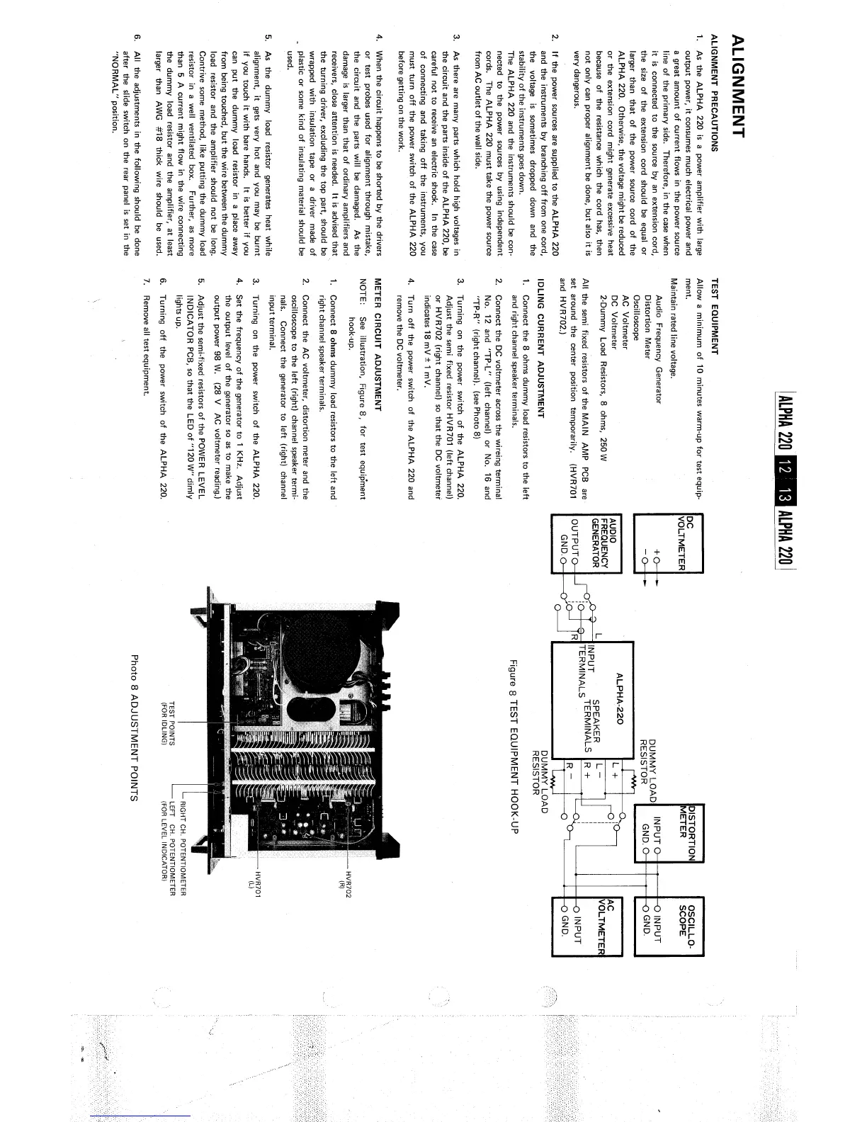
IDLING CURRENT ADJUSTMENT
1. Connect the 8 ohms dummy load resistors to the left
and right channel speaker terminals,
Connect the DC voltmeter
across the wireing terminal
No. 12 and "TP-L"
(left channel) or
No, 16 and
TP-
R"
(right channel). (see Photo 8)
Turning on the power
switch of the
ALPHA 220.
Adjust the semi fixed
resistor HVR701 (left channel)
or HVR702 (right channel) so that the DC voltmeter
indicates 18 mV:t 1 mV.
Turn off the power
switch of the
ALPHA 220 and
remove the DC voltmeter.
METER CIRCUIT ADJUSTMENT
NOTE: See illustration
, Figure 8
, for test equipment
hook-up.
Connect 8 ohms dummy load
resistors to the left and
right channel speaker terminals.
Connect the AC voltmeter
, distortion meter and the
oscilloscope to the left (right) channel speaker
termi-
nals, Connect the generator to left
(right) channel
input terminal.
Turning on the power
switch of the
ALPHA 220.
Set the frequency of the
generator to 1 KHz, Adjust
the output level of the generator so as to
make the
output power 98 W. (28 V AC voltmeter reading,
Adjust the semi-
fixed resistors of the
POWE R LEVEL
INDICATOR PCB
, so that the LED of "
120W" dimly
lights up,
Turning off the power
switch of the
ALPHA 220.
Remove all test equipment.
VOLTMETER
AUDIO
FREQUENCY
GENERATOR
OUTPUT
GND.
DISTORTION
METER
---
INPUT
GND.
DUMMY LOAD
RESISTOR
ALPHA-
220
L I
IN PUT
SPEAKER
TERMINALS TERMINALS
R +
DUMMY LOAD
RESISTOR
Figure 8 TEST EQUIPMENT HOOK-
TEST POINTS
(FOR IDLING)
RIGHT CH. POTENTIOMETER
LEFT CH. POTENTIOMETER
(FOR LEVEL INDICATOR)
Photo 8 ADJUSTMENT
POINTS
OSCILLO-
SCOPE
INPUT
GND.
VOLTMETER!
INPUT
GND.