ALPHA
220
Now
, suppose the plus wave (plus part) of
signal has
been inputted
, the current of Qp1
increases and the
voltage at both ends of
RE 1 become high
, resulting
in the voltage between
CBJ
point and
OUTPUT.
At that time
, the voltage at both ends of
R1 becomes
high because current flows R1 -+ D1 -+ Q1,
causing
the potential at
(Q
point to lower and the voltage of
03 between collector and emitter to rise.
As a result
, the voltage between
CBJ
and
rises and
Qp2 is kept from being cut-off.
From another point of view
, the voltage drops at the
emitter resistor RE
1 (these resistors
are indispensable
to protect
transistors in stabilizing bias of the output
stage or at the time of abnormal
current flowing)
is cancelled by the drop at R
1, thus protecting Qp2
from becoming zero or anti-
bias.
In the same manner
, when the minus wave (minus
part) of signal has been inputted
, current flows
Q2 -+
D2 -+ R2, resulting in a rise of
VCE at Q4 thus protect-
ing Qp1 from being cut-off.
DC SERVO CIRCUIT
DC amplification is the most
advanced form adopted
for audio
amplifiers as there is no
phase lag over all
the range from DC to audio frequency.
However
, in a perfect
DC amplifier (which is an am-
plifier having no coupling capacitors in its input part
and N FB loop), a DC drift is
caused in case a direct
current is inputted or
when the DC
balance between
each element has been
los~ due to
temperature rise
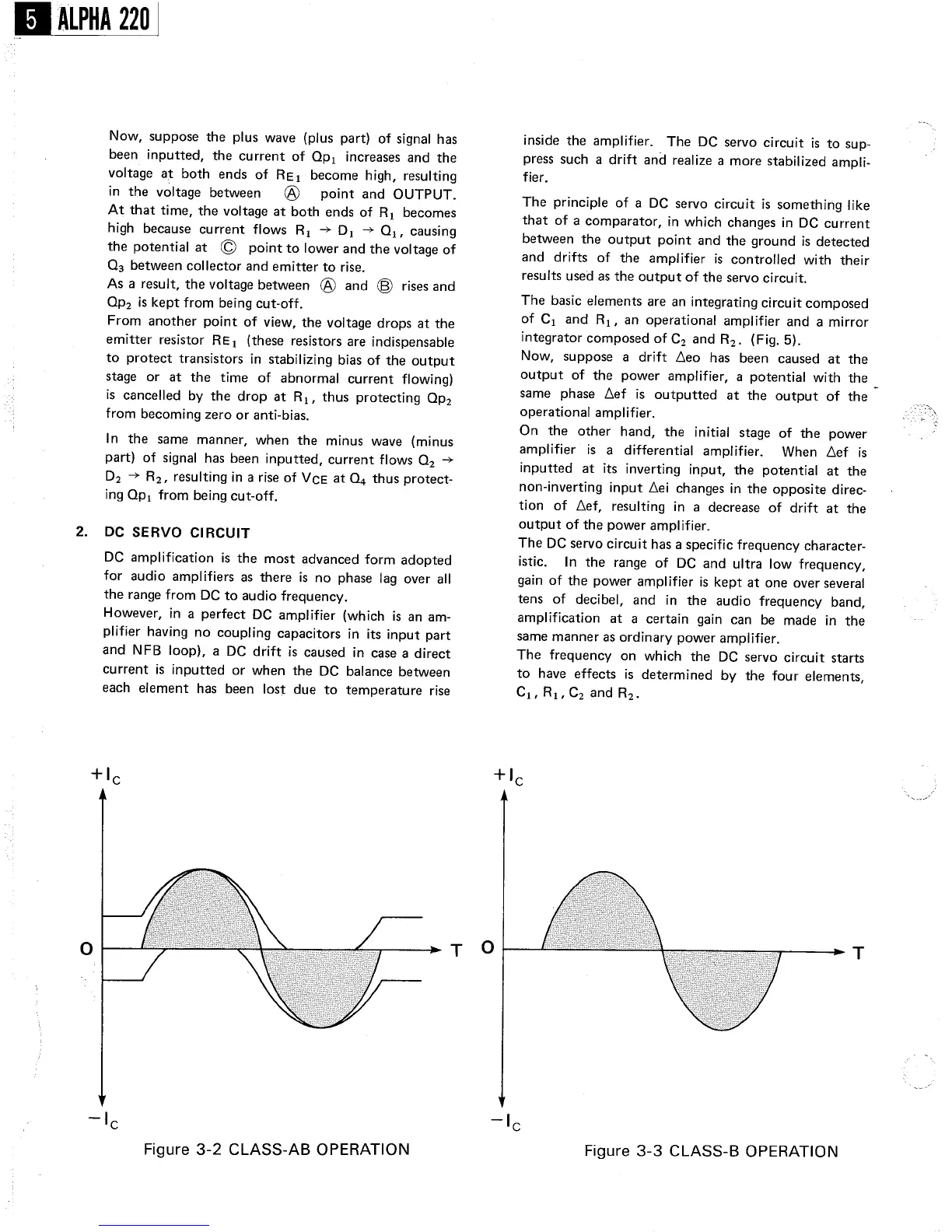
Figure 3- 2 CLASS-
AB OPERATION
inside the amplifier. The
DC servo circuit is to
sup-
press such a drift and
realize a more stabilized ampli-
fier.
The principle of a
DC servo circuit is something like
that of a comparator
, in which changes in DC current
between the output point and the ground
is detected
and drifts of
the amplifier
is controlled with their
results used as the output of the servo circuit.
The basic elements are an integrating circuit composed
of C1 and R1' an
operational amplifier and a mirror
integrator composed of C2 and R2. (Fig. 5).
Now
, suppose a
drift
lleo
has been caused at the
output of the power amplifier
, a potential with the
same phase llef
is outputted at the output of the
operational amplifier.
On the
other hand
, the
initial stage of the
power
amplifier is a
differential amplifier.
When llef
inputted at its
inverting input
, the potential at the
non-
inverting input llei changes in the opposite direc-
tion of llef
, resulting in a decrease of
drift at the
output of the power amplifier.
The DC servo circuit has a specific frequency character-
istic. In the range of
DC and ultra low
frequency,
gain of the power amplifier is kept at one over
several
tens of decibel
, and in the audio frequency band
amplification at a
certain gain can be
made in the
same manner as ordinary power amplifier.
The frequency on which the DC
servo circuit starts
to have
effects is
determined by the four elements
C1,
R1,
C2andR2.
Figure 3-
3 CLASS-
B OPERATION