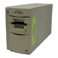
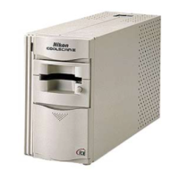
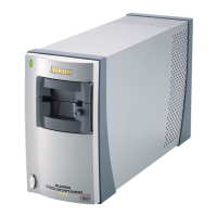
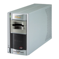
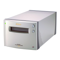
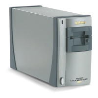
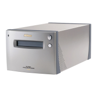
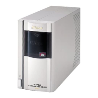
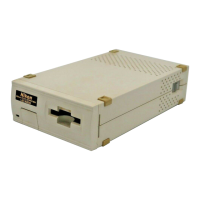
Maintenance Service on Nikon CoolScan Slide Scanner
Summary: Major disassembly of scanner mechanism and controller circuit
board, lubricate and manually actuate slide rails and stepper motors.
Time to perform: about 2 hours
The X-axis scanning runs on three slide rails and a stepper motor. The Z-axis Autofocus runs on 2
slide posts, 2 forked sliders and a stepper motor. Both of these mechanisms require lube until they
move easily and smoothly. Circuit board removal is required as most of the mechanism to be lubed
is on the left side. Only one X-axis slide rail is accessible from the right side, making it an
incomplete job. Clean sensor lens and two front-sided mirrors, as needed.
Statement of Warranty, Limits of Liability agreement, and other WARNINGS is included in
Section IV, near the end of this document.
I. Qualify that the unit is operational, incoming inspection
0) check to see that no data cable is attached and that jacks are not damaged or contact pins are bent
or corroded.
1) make sure that unit turns on with just AC plugged in. See that green light turns on, blinks and
stays steady. Position unit in vertical position with power switch on top.
2) during the blinking phase, the unit is booting up and goes through mechanism qualification
steps, see if you can hear any buzzing where stepper motors are moving the scanner mechanism.
Testing of Autofocus is first and X-axis scan is second.
3) look inside the slide module throat and see if you can see any narrow strip of light from the LED
light module located in the upper case near where the inner edge of the slide mount would be.
Symptoms:
4) if any of the mechanisms doesn't move during the qualification step, the green light changes to a
rapid blink (about every half sec) and then steady green at the end of the boot sequence.
This negative failing rapid blink diagnostic will show up by the NikonScan app not recognizing
that a correctly booted scanner is attached...the infamous "Nikon Scan was unable to find any
active devices" dialog box message.
If yes to all four, then the unit just needs to be lubricated with Teflon and lens and mirrors cleaned
with alcohol and or aqueous lens cleaner.
5) if there is slow blinking (about once per second) during boot for about 15 sec and then a steady
green, then the slide scanner has booted normally and this maintenance and cleaning procedure is
not required at this time.