CONTENTS
Contents ............................................................................................................................................................................... iii
Figures ..................................................................................................................................................................................iv
Section 1 — Introduction ................................................................................................................................................ 1-3
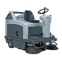
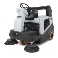
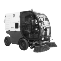
SR 1900 Deluxe Cab Options ...............................................................................................................................................1
Other Manuals Available ........................................................................................................................................................1
General Notes .......................................................................................................................................................................1
Cautions and Warnings .........................................................................................................................................................2
Symbols .................................................................................................................................................................................2
General Safety Instructions ...................................................................................................................................................2
Technical Specifi cations ........................................................................................................................................................3
Section 2 — Know Your Machine ................................................................................................................................... 4-6
Cab Controls ..........................................................................................................................................................................4
Heating System Components ................................................................................................................................................5
Air Conditioning System Components ...................................................................................................................................6
Section 3 — Maintenance ...................................................................................................................................................7
Maintenance Schedule ..........................................................................................................................................................7
To Clean and Replace the Cab Filter .....................................................................................................................................7
Section 4 — Heating System ........................................................................................................................................ 8-12
General System Overview .....................................................................................................................................................8
Electrical Circuit Overview .....................................................................................................................................................8
Heater Blower Motor ..............................................................................................................................................................8
Heater Temperature Control ..................................................................................................................................................8
Electrical Troubleshooting ................................................................................................................................................9-11
Symptom: The heater Blower Motor will not run. ...................................................................................................................9
Symptom: There is no cab heat, or the cab heat cannot be controlled. .........................................................................10-11
To Eliminate Air Locks from the Cooling System .................................................................................................................12
Cooling System Vacuum Filler .............................................................................................................................................12
Purge the Heater Circuit ......................................................................................................................................................12
Section 5 — Air Conditioning System ....................................................................................................................... 13-20
General System Overview ...................................................................................................................................................13
Electrical Circuit Overview ...................................................................................................................................................13
Blower Motors ......................................................................................................................................................................13
Condenser Fan, Thermostat, Pressure Switch and Compressor Motor ..............................................................................14
Electrical Troubleshooting ...................................................................................................................................................15
Symptom: One or both of the Blower Motors will not run. ...................................................................................................15
Symptom: The Blower Motors run but there is no cold air coming out of the Evaporator-Heater Unit. ...............................16
Component Troubleshooting ...............................................................................................................................................17
Compressor Motor Hydraulic Valve (L10) ............................................................................................................................17
Accessory (Gear) Hydraulic Pump ......................................................................................................................................17
Compressor Relay (K10) .....................................................................................................................................................18
Binary Pressure Switch (S34) ..............................................................................................................................................19
Thermostat (S33) .................................................................................................................................................................20
Section 6 — Appendix .......................................................................................................................................................21
Cab Electrical Wiring Diagram .............................................................................................................................................21
Cab Electrical Ladder Diagram ............................................................................................................................................22
Heating and A/C System Plumbing and Hydraulic Schematic .............................................................................................23
FIGURES
Figure 1-1 — SR 1900 Cab Height ........................................................................................................................................3
Figure 2-1 — Cab Controls ....................................................................................................................................................4
Figure 2-2 — Heating System Components ..........................................................................................................................5
Figure 2-3 — Air Conditioning System Components .............................................................................................................6
Figure 3-1 — Cab Filter .........................................................................................................................................................7
Figure 4-1 — Valve Assembly Connector Pins ....................................................................................................................10
Figure 4-2 — Valve Assembly Hose Functions ...................................................................................................................12
Figure 5-1 — Compressor Motor Hydraulic Valve ...............................................................................................................17
Figure 5-2 — Compressor Relay .........................................................................................................................................18
Figure 5-3 — Checking Continuity through the Binary Pressure Switch .............................................................................19
Figure 5-4 — Checking Continuity through the Thermostat ................................................................................................20
 Loading...