7 / 14
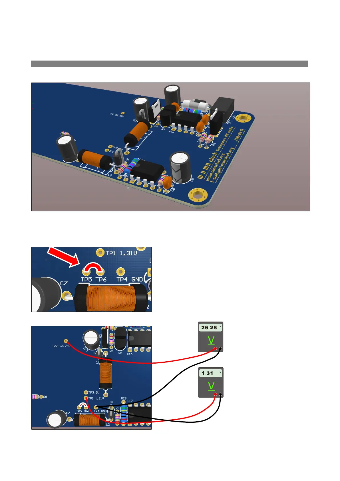
Please check the board to make certain that the parts are all soldered correctly, then
for testing, place a wire jumper between TP5 and TP6 as shown below:
Connect the power adapter. The voltage
measured between TP2 and TP4 should be
about 26.25 VDC; the voltage measured
between TP1 and TP4 should be about
1.31 VDC.
Please remove the jumper between TP5 and
TP6 after measuring the voltage.