6 7
D. Installation Procedure/Connections E. Control Panel Settings and Adjustments:
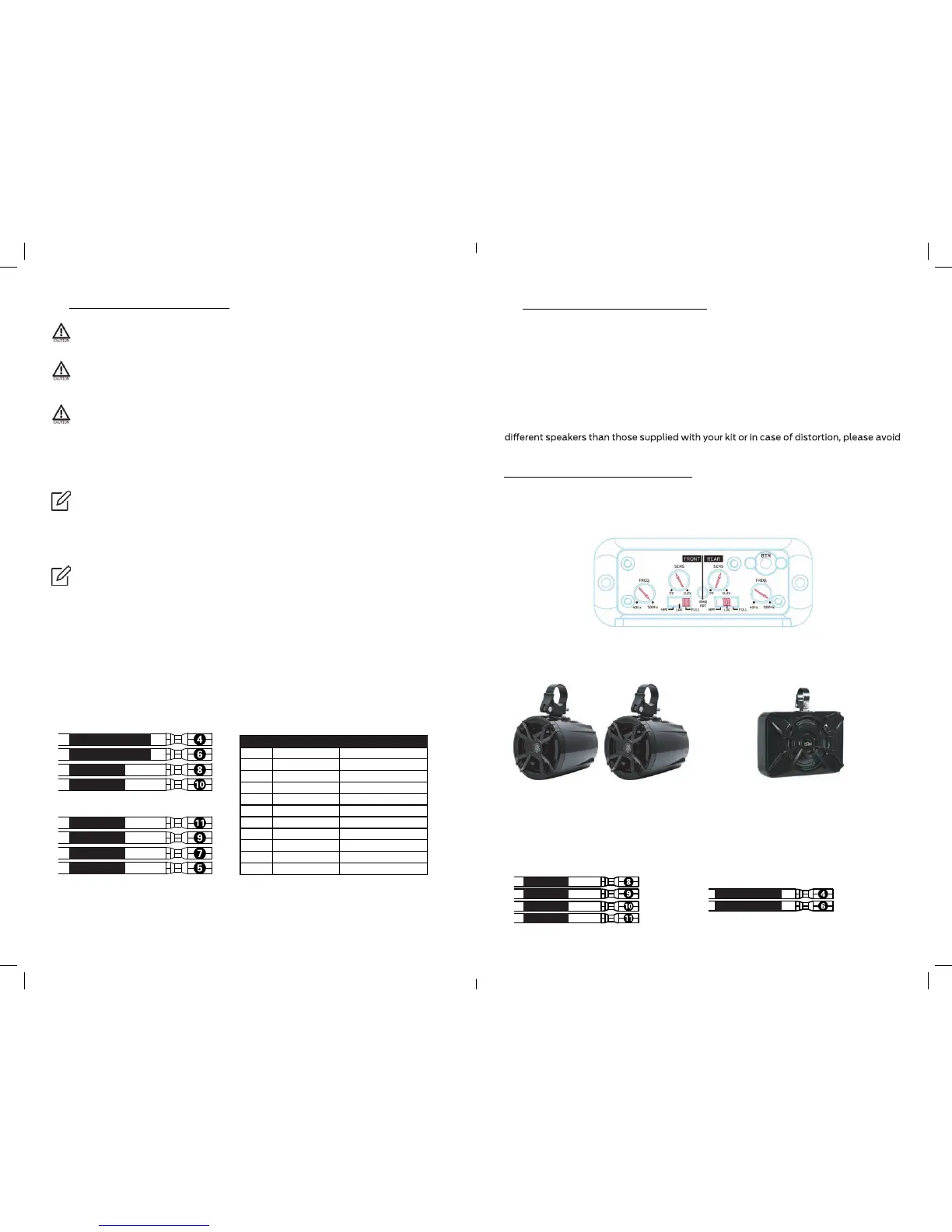
This is your default control panel settings:
If you feel unsure about installing this system yourself, have it installed by a
qualified technician.
Before installation Disconnect the NEGATIVE battery post connection and secure
the disconnected cable to prevent accidental reconnection during installation. This
is an essential safety precaution during installation!
Avoid running power wires near the low-level input cables, antenna, power leads,
sensitive equipment or harnesses. The power wires carry substantial current and
could induce noise into the audio system.
1. Connect the RED power lead to the positive (+12V) battery post.
The amplifier’s settings and controls are located on the side panel beneath a gasketed,
protective cover. Remove the five Allen head screws from the center panel to access the
controls and make adjustments. Replace cover when finished and mount the amplifier.
Your NA4 amplifier’s control panel was preset to fit the N5 Full-range speakers and
NSUB subwoofer supplied with the NUTV5/NUTV5-S stereo system. Unless you use
adjusting the gain and crossover settings of the amplifier.
These settings are true for both NUTV5 and NUTV5-S models. Even if you bought the
NUTV5 without the NOAM NSUB, your amplifier’s REAR channels are still set to the
NSUB subwoofer bridge mode.
Since the control panel is preset, please make sure you connect your speakers
to the right output channels.
IMPORTANT! Your NA4 amplifier control panel was preset to work as part of the
NUTV5 / NUTV5-S audio system.
3. Fuse. Your NA4 already includes a 40A fuse. The NA4 power wires are 8’ long, while the
Fuse housing located on the Red/Positive power wire at 5’ of wire from the amplifier.
4. Connect the NR male controller DIN plug to the NA4’s female DIN plug.
* Powering the NA4 amplifier. Long pressing your NR controller’s power button for few
seconds will trigger both the NR controller and the NA4 amplifier ON/OFF.
5. Run the speakers wires to the amplifier’s output.
Make sure about correct polarity when connecting your speakers to the amplifier.
speaker’s Red wire (+) should connect to color (+) output channels.
speakers’s Black wire (-) should be connected to color / Black (-) output channels.
Speaker connection color codes:
6. If you haven t already done so, mount the amp now.
7. Now you should be good to go and play tunes for the first time.
2. We strongly recommend to run the Black/Ground power cable to the negative (-12V)
battery post.
Blue / Remote Turn-On wire is not required for installing or running your NA4
amplifier. The NR controller is able to power trigger your amplifier
You have plenty of power wire length before the fuse holder (5’). Strive to leave
no more than 18” (45.7 cm) of wire between the fuse holder and the battery
positive (+12V) terminal. You can cut the remaining wire.
FRONT – N5 Speakers
(or other full range speakers)
REAR – NSUB subwoofer
The FRONT channels are set to power
your N5 full range speakers. Make sure
you connect the pair of N5 speakers to
the FRONT output channels.
The REAR channels are set to power your
NSUB subwoofer. Make sure you connect
the NSUB subwoofer to the REAR output
channels.
Rear Left - / Sub -
Rear Right + / Sub +
Front Left -
Front Right +
Front Right -
Front Left +
Rear Right -
Rear Left +
Red
Black
Blue
Green/Black
1
2
3
4
+12V
Ground
Remote
Rear Left - / Sub -
Purple
6
Rear Right + / Sub +
White/Black
8
Front Left -
Grey
10
Front Right +
Grey/Black
11
Front Right -
White
9
Front Left +
Purple/Black
7
Rear Right -
Green
5
Rear Left +
WIRE# COLOR CODE FUNCTIONE
Front / Right + Grey
Front / Left + White
Front / Left - White/Black
Front / Right - Grey/Black
Rear / Right + // Sub+ Purple
Rear / Left - // Sub- Green/Black