Do you have a question about the Noblelift PS 12 TSL and is the answer not in the manual?
Essential safety guidelines for maintenance personnel to prevent injuries and equipment damage during service.
Provides conversion factors for various units of length, area, volume, and weight for technical specifications.
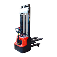
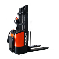
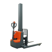
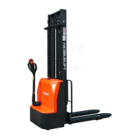
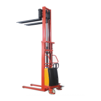
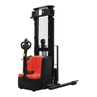
Identifies and labels the primary parts of the equipment, aiding in component recognition.
Details critical technical specifications and performance data for different models of the equipment.
Presents the schematic diagram of the equipment's electrical system, showing component connections.
Illustrates the main wiring harness layout and component connections for the equipment's electrical system.
Details the components and assembly of the drive wheel system, including brake and gearbox.
Describes the pump station system components and their assembly, crucial for hydraulic operations.
Provides a step-by-step guide for safely removing and installing the vehicle's battery unit.
Explains the procedure for maintaining lead-acid batteries, including water supply and potential issues.
Describes how to interpret the battery charge level indicator and its segments.
Details the components and functions of the electricity meter, including its connectors and indicators.
Introduces the charger's suitability for various electric vehicles and its general capabilities.
Outlines the correct procedure for charging the vehicle's battery using the specified charger.
Details the main controller unit, including its part number and associated components like contactors and fuses.
Illustrates the components of the display assembly, including the electricity meter and switches.
Step-by-step instructions for removing and replacing the electric meter on the equipment.
Guide for replacing the emergency stop button, involving disassembly of control panel components.
Instructions for removing and replacing the universal key switch used for equipment ignition and control.
Procedure for replacing fuses (Fuse 1, Fuse 2, Fuse 01) by accessing and opening the fuse box.
Detailed steps for removing and replacing the equipment's contactor, including necessary tools.
Instructions for replacing the main electric control unit, including wiring disconnection and component removal.
Step-by-step guide to removing and replacing the relay components within the electrical system.
Procedure for removing and replacing the micro switch, detailing component access and wiring disconnection.
Instructions for replacing the magnetic switch, involving unplugging harness connectors and removing ties.
Guidance on replacing the main wiring harness, emphasizing correct plug correspondence and numbering.
Steps for replacing the hydraulic pump station, ensuring the pallet rack is lowered first.
Procedure for draining and refilling hydraulic oil, including recommended types and quantities.
Instructions for replacing the hydraulic system filter, usually accessed after pump removal.
Steps for replacing carbon brushes, typically found in motors, involving cover removal and screw unscrewing.
Procedure for adjusting the oil pump pressure using specific tools and settings.
Detailed steps for replacing the outer hydraulic cylinder on both the right and left sides.
Instructions for replacing the middle hydraulic cylinder, involving pin removal and hoop unscrewing.
Guide for replacing sealing rings on the outer oil cylinder, including O-rings and dust rings.
Steps for replacing sealing rings on the middle hydraulic cylinder, involving dust, retaining, and Y-type seals.
Illustrates the components that make up the tiller and handle assembly of the equipment.
Procedure for replacing the main printed circuit board (PCB) in the tiller housing.
Instructions for removing and installing the air spring for the tiller assembly.
Specific steps for mounting the air spring onto the tiller, including securing bolts.
Guide for replacing the interlock switch, involving handle housing disassembly and connector unplugging.
Step-by-step process for replacing the small drive wheel, including jacking and bolt removal.
Instructions for changing the lubricating oil in the drive wheel gearbox, including oil injection and drain points.
Procedure for removing and replacing sensors used in the drive wheel system.
Details the process of replacing or adjusting the braking components of the drive wheel assembly.
Steps for disassembling and maintaining the wheelset components, including axle and bearings.
Procedure for maintaining the steering group, involving clamp spring and axle removal.
Step-by-step guide for replacing the bearing wheels on the equipment, including pin and axle removal.
Instructions for replacing the chain, involving lifting the rack, removing pins, and splitting the chain.
Guidance on maintaining the chain, including tightening, cleaning, and lubrication procedures.
Steps for safely removing the mast assembly, involving split pin removal and frame lifting.
Procedure for replacing rollers within the mast system, including snap spring and gasket removal.
Instructions for adjusting the roller gap in the mast system using bolts.
Identifies various labels and their locations on the equipment for the European market.
Identifies various labels and their locations on the equipment for the American market.
Comprehensive list of maintenance tasks with recommended intervals for hydraulic, mechanical, electrical, and battery systems.
Troubleshooting guide detailing common failures, their causes, and recommended maintenance actions.
| Load Capacity | 1200 kg |
|---|---|
| Lift Height | 3500 mm |
| Overall Length | 1780 mm |
| Overall Width | 800 mm |
| Weight | 760 kg |
| Power Source | Electric |
| Battery Capacity | 210 Ah |
| Lifting Speed (no load) | 0.4 m/s |
| Lowering Speed (full load) | 0.5 m/s |