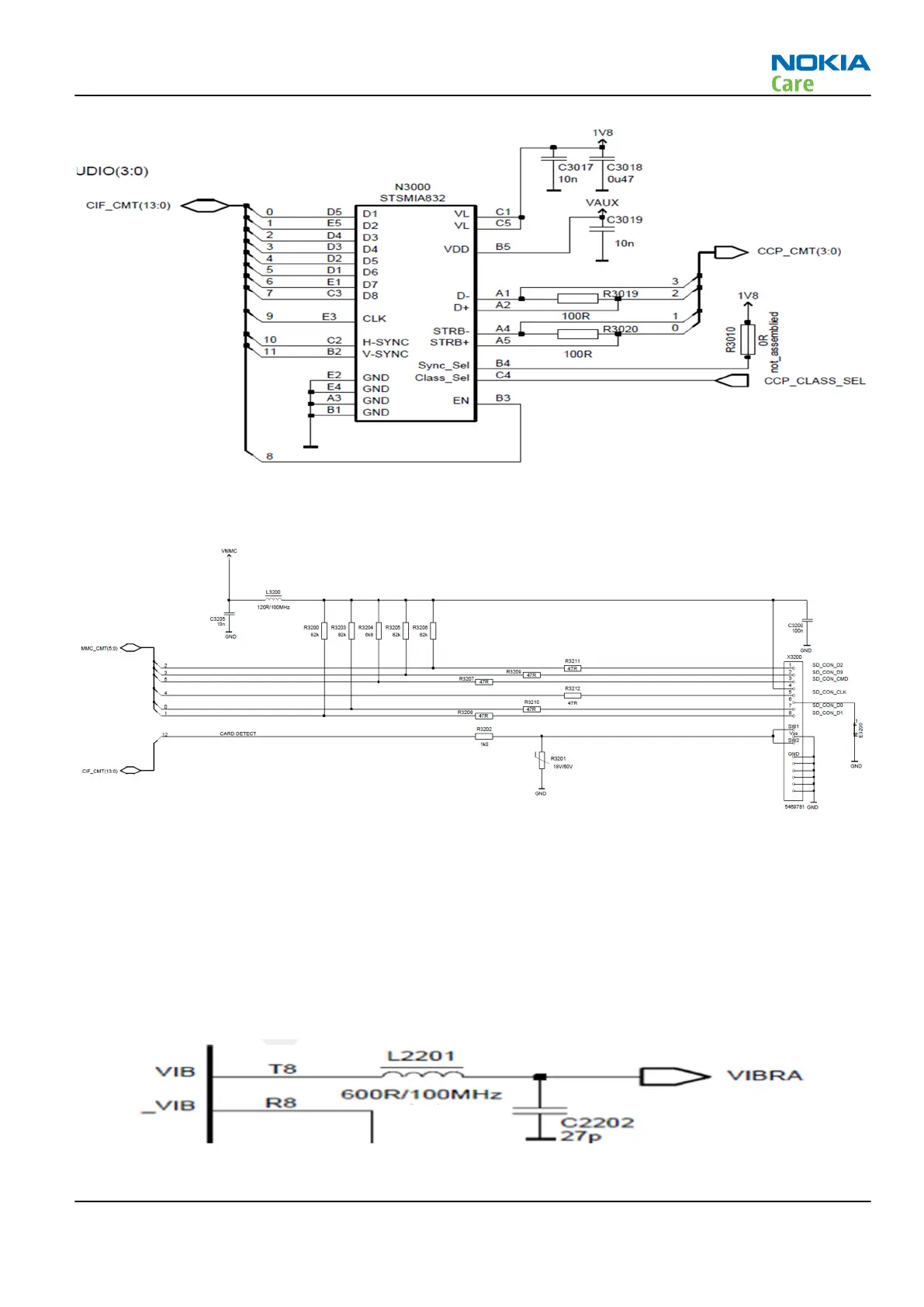
Figure 65 Camera de-serializer for serial camera module
Baseband electrical interfaces: Memory card
Figure 66 SD-card interface
The XGold213 MMCI interface is connected to the SD-card connector through an ASIP R3200 providing EMI
filtering and ESD protection. A build in switch in the connector X3200 provides a logic signal for detection of
card insertion and removal.
Baseband electrical interfaces: Vibrator
The vibrator function is supported using the VIB driver in the X-GOLD213. This driver features a VBAT supplied
push-pull output stage which is intended for driving a vibrator motor. The engine also supports vibrating
using the 3-in-1 multi-actuator device.
Figure 67 Vibrator circuits
RM-761; RM-799; RM-800
System Module
Issue 1 COMPANY CONFIDENTIAL Page 5 – 23
Copyright © 2011 Nokia. All rights reserved.