9
3.1
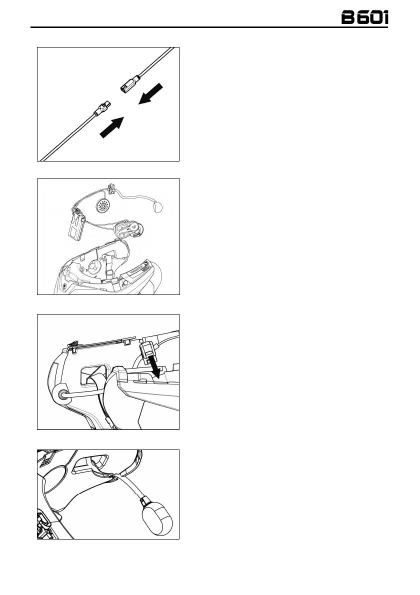
Installing the B601 system on the helmet
Fig. 2
• Hook up the microphone connector to the other
end, following the directions of the arrows (Fig.
2).
N.B.
: You can adjust the position of the microphone.
For instructions on how to do this, please see
chapter. 3.2.
Fig. 3
• Place the system in the special housing in the
back of the helmet, pushing it all the way into
the groove (Fig. 3).
Fig. 4
N.B.: For positioning of the wiring and of the
microphone in the N100-5 helmet, follow the
instructions provided in the dedicated box.
• Fix the cable inside the helmet and make sure
the right fixing clip snaps into its housing (Fig. 4).
Fig. 5
• Position the microphone in the housing on the
right of the helmet, inserting the metal boom in
the groove found in the chin guard coupling
frame (Fig. 5).
Caution
: make sure that the side of the
microphone support with the writing “
n
” is facing
inward.
 Loading...