EN
10
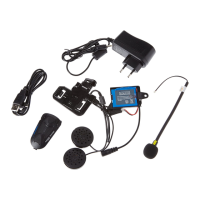
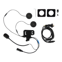
Fig. 14
Fig. 15
Fig. 16
Fig. 17
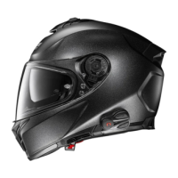
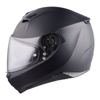
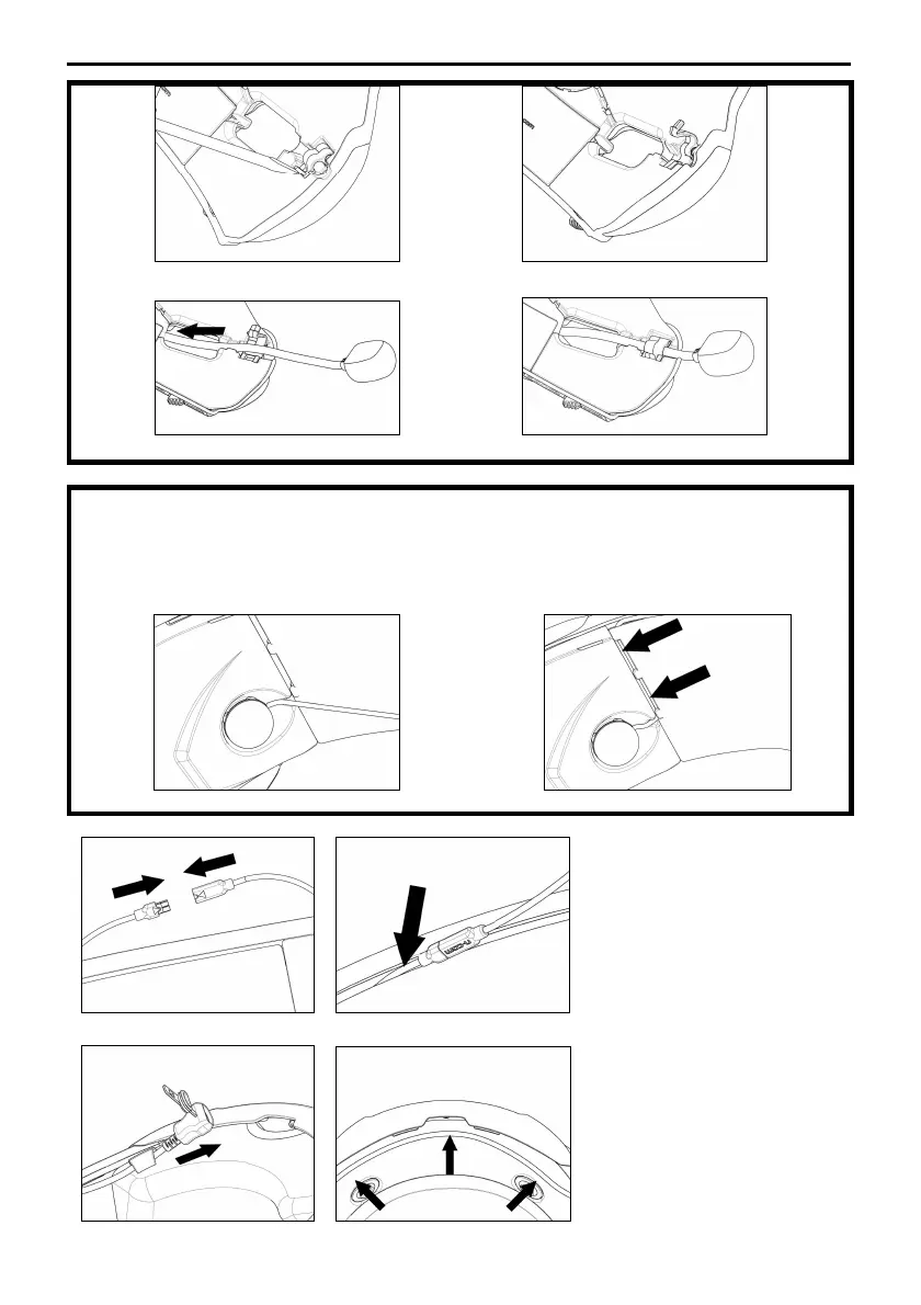
ONLY FOR X-903 HELMETS
• Hook up the specific microphone for full-face helmets in its seat in the chin guard (Fig. 18).
• Position the microphone wire in the vertical groove (Fig. 19) and afterwards behind the cheek pad lining. If
necessary, lift up the groove tabs and the cheek pad lining using a flat head tool (supplied as standard
equipment).
Fig. 18
Fig. 19
Fig. 20
Fig. 21
•
Hook up the microphone to the
connector coming out of the e-
Box (Fig. 20).
•
Position the wiring and the
connectors behind the cheek
pad lining, lifting it wi
of a flat head tool (Fig. 21).
Fig. 22
Fig. 23
•
Pass the USB mini wire through
the elastic band found on the
comfort padding (Fig. 22).
•
Position the wiring in the rear
part of the helmet (Fig. 23).
 Loading...