Component Check-Out Procedures
LP Gas
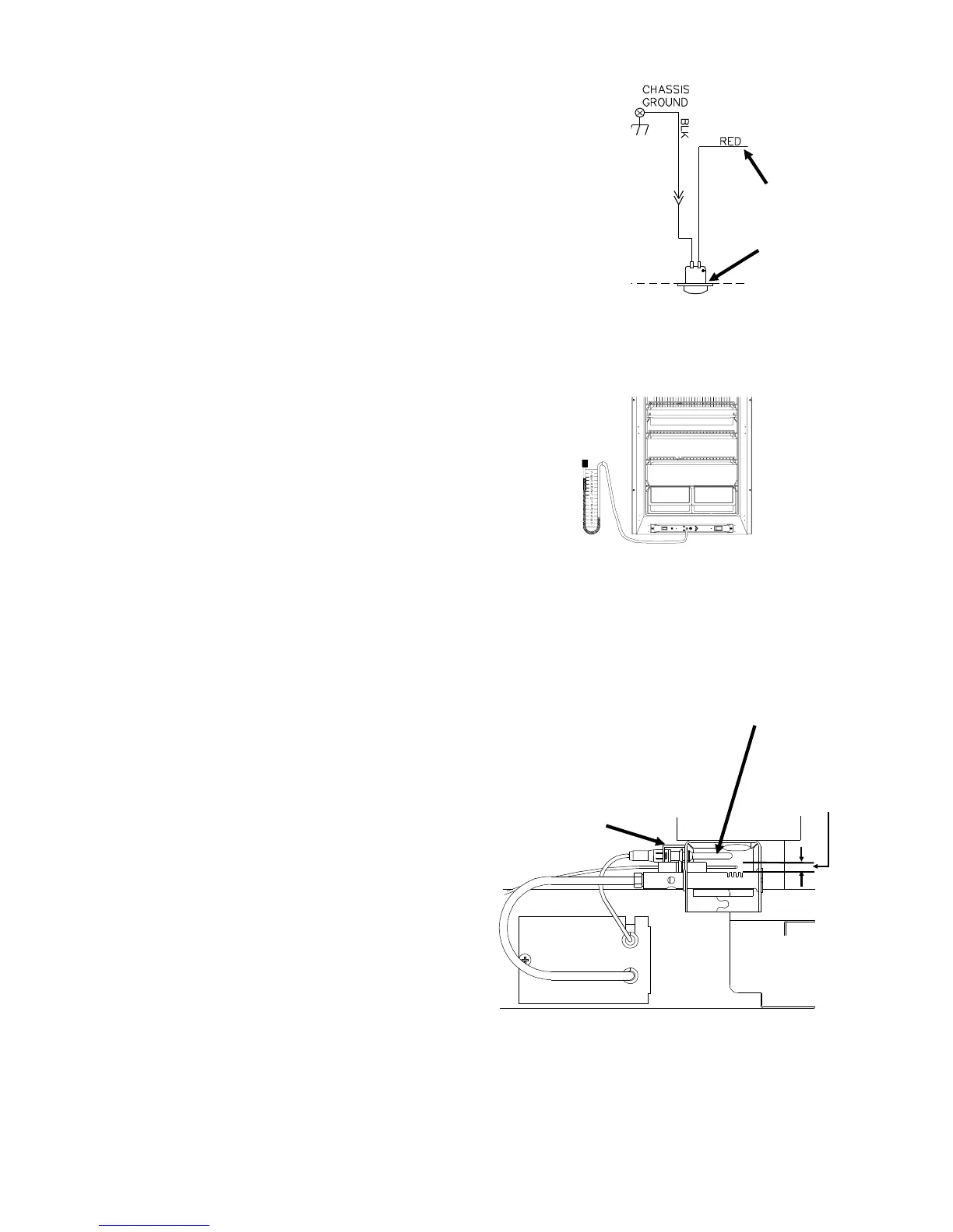
Flame Meter Check-Out-Figure 12
• Use the control panel and control bracket removal
procedure to gain access to the flame meter leads.
• Insure the red flame meter lead is connected to the
thermocouple adapter and the blue flame meter
lead is connected to the black ground wire.
• Disconnect the flame meter leads.
• Measure the resistance of the flame meter. If the
resistance does not measure from 8 to 12 ohms,
replace the meter.
Checking Gas Pressure at the Combina-
tion Control-Figure 13
• The combination control modulates the gas pres-
sure between .8 inches W.C. and 10.9 inches W.C..
• Access to the combination control is gained by
removing the control panel and the control bracket
mounting screws. See "Control Panel Removal
Procedure" (Figure 10) on page 13.
• Use a 3/16" allen wrench to remove the pressure
tap plug. Using a 1/8" NPT nipple, connect a U-tube
manometer to the exposed port.
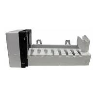
Burner Assembly-Figure 14
• Remove the burner box to gain access to the
burner.
• Pull the cover slightly forward and slide it towards
the gas valve.
• Check the electrode position (align over 2nd slot of
the burner) and the gap of the ignition electrode
(1/8" - 3/16" above the burner).
• Check for and remove any foreign material on
either the ignition electrode and the thermocouple.
• Insure the thermocouple is positioned properly into
the flame.
• Insure the retainer clip is properly installed and is
securing the thermocouple to the burner bracket.
To Thermocouple
adapter
BLU
Figure 12
Flame Meter
Figure 13
Retainer
Thermocouple
Figure 14
1/8" to
3/16" Gap
14