Component Check Out Procedures-AC
Electric
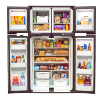
Note: Before attempting to trouble shoot the refrigera-
tor, make sure the AC outlet (Figure 8) is supplying
between 108 and 132 volts.
5 Amp Fuse Check-Figure 8
• If 120 VAC is not present at the heater terminals,
check the 5 amp fuse for continuity.
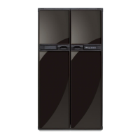
Heater Element Measurement-Figure 9
• Disconnect heater leads from refrigerator.
• Set ohmmeter to lowest range and measure resis-
tance across heater leads. Heater resistance should
fall between 38 to 43 ohms.
Checking for Heater Electrical Leakage-
Figure 9
• Disconnect heater leads from refrigerator.
• Set Ohmmeter to highest range.
• Connect one of the meter probes to one of the heater
leads. Touch the remaining meter probe to the case
of the heater (ground). If the meter reading fluctu-
ates, replace the heater.
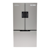
Combination Control Check-Out Proce-
dures-Figures 10-12
Control Panel Removal Procedure-Figure 10
• Remove the mode selection and thermostat knobs
(A).
• Remove the five phillips head screws (B).
• Pull control panel away from the refrigerator.
• Remove the two phillips head screws holding the
control mounting bracket in place (C).
• Pull control mounting bracket forward to gain access
to the refrigerator controls.
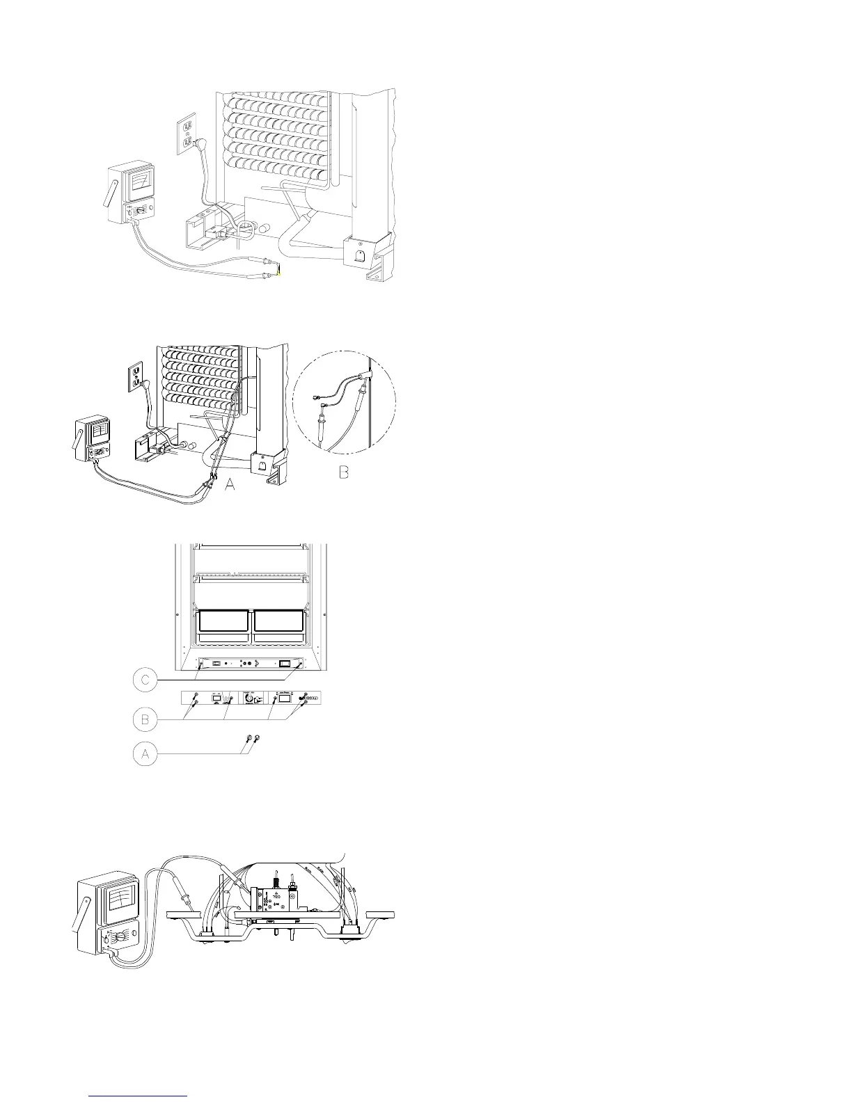
Check for 120 volt AC at both terminals of the combi-
nation control.
• If there is a 0 volt reading at both terminals, check
wiring connections. If wire connections are found to
be O.K., replace combination control.
• If 120 volts reading is at one (1) terminal only, replace
the combination control.
Figure 8
Figure 9
Figure 10
Figure 11
13