board located at the rear of the refri
erator
Fi
ure
9
. The 12 volt DC should enter the refri
erator’s en-
closure near the refri
erator’s power suppl
board.
The 12 volt DC connects at
2
one
uarter inch
uick connects. The positive DC input lead connects
to terminal J4, and the DC
round input lead con-
nects to terminal J3.
CAUTION: Correct polarity must be ob-
served when connecting the DC supply.
Do not use the chassis of the refrigerator
or the vehicle frame as one of the conduc-
tors. Connect DC supply wires at the bat-
tery and route to the refrigerator.
The distance the current travels from the batter
to
the refri
erator dictates the wire size. Undersized
wire can result in a volta
e drop, which will affect the
watta
e output of the DC heater and result in re-
duced refri
erator performance. Norcold recommends
the installation of a fuse in the suppl
wirin
between
the batter
and the refri
erator. For optimum protec-
tion, install the fuse as close to the batter
as possi-
ble.
WARNING: A circuit overload can result in
an electrical fire when undersized wires or
improperly sized fuses are used. To pre-
vent a possible electrical fire, follow
R.V.I.A. A119.2 Standards, Norcold’s wire
size and fuse specifications, or applicable
state and local codes.
TABLE 3
12 VOLT SUPPLY WIRING AND FUSE SIZE
6162, 6182
662, 682
6052, 652
6163, 6183
663, 683
6053, 653
min.
wire
size
max.
fuse
size
min.
wire
size
max.
fuse
size
Min.
wire
size
max.
fuse
size
0 - 20’ 18
AWG
6 Amp 10
AWG
30
Amp
12
AWG
20
Amp
over
20’
18
AWG
6 Amp 8
AWG
40
Amp
10
AWG
30
Amp
If a wire size is installed which is lar
er than the
minimum size indicated the table above, it must be
fused in accordance with the R.V.I.A. A119.2 stand-
ard or local
overnin
codes.
Hypot Test
A Dielectric Stren
th test
h
pot
has been con-
ducted at the factor
; this refri
erator does not re-
uire an additional test. If h
pot tests are conducted
on the vehicle’s 12 volt circuit, the 12 volts
must
be
disconnected from the refri
erator to protect the
flame i
nition circuit.
Testing the Vehicle’s Gas Supply Piping
When installation of the refri
erator is complete, the
propane
as suppl
pipin
must be inspected and
tested for leaks from the refri
erator to the main
as
suppl
tank. Use a leak detection solution.
Do not
test for leaks with an open flame.
If compressed air is used for leak testin
, the
au
e
pressure must not exceed 1/2 pound per s
uare inch
14 inches water column
.
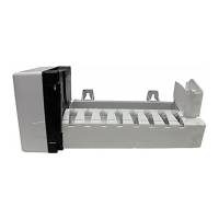
The appliance and its individual shut-off valve
Fi
-
ure 10
must be disconnected from the
as suppl
s
stem durin
an
pressure testin
of that s
stem at
test pressures
reater than 1/2 psi
14 inches water
column
.
The appliance must be isolated from the
as suppl
s
stem b
closin
its individual manual shut-off valve
Fi
ure 9
durin
an
pressure testin
of that s
stem
at test pressure e
ual to or less than 1/2 psi
14
inches water column
.
Check the
as pressure to the refri
erator without
other
as appliances operatin
. The pressure should
not exceed 11 inches water column. With other appli-
ances operatin
the pressure should not be less than
10.5 inches water column.
Check Out - Flame Failure Safety Device
Before placin
the refri
erator into operation, the
as safet
device must be tested
see Operatin
In-
structions on pa
e
. The purpose of the
as safet
device is to prevent the escape of unburned
as from
the burner if the burner flame is extin
uished. While
there is a flame present at the burner, disconnect the
electrode wire to i
nition module
see Fi
ure 11
.
Fi
ure 10
10