INSTALLATION INSTRUCTIONS
Certification and Code Requirements
The refri
erators described herein are certified un-
der the latest edition of ANSI Z21.19 Standards b
the American Gas Association
A.G.A.
for installa-
tion in mobile home or recreational vehicle and ap-
proval b
the Canadian Gas Association
CGA
.
Installation must be made in accordance with these
standards and with the installation instructions pro-
vided in this manual for the Norcold factor
warrant
to be in effect.
Installation must conform with local codes, or in the
absence of local codes, with the followin
standards
as applicable:
In the United States:
a. National Fuel Gas Code, ANSI Z223.1.
b. Manufactured Home Construction and Safet
Standard, Title 24 CFR, Part 23-80.
c. Standard for Recreational Vehicles,ANSI
A119.2, latest edition.
When an external electrical ener
is utilized, the
refri
erator must be electricall
rounded in accord-
ance with local codes, or in the absence of local
codes, the National electrical Code, ANSI/NFPA 70.
In Canada:
a. Current CGA B149.1 and B149.2 installation
code for Propane Appliances and E
uipment..
b. Current CSA Z240.4.2 installation code for Pro-
pane Appliances and E
uipment in Recrea-
tional Vehicles.
c. Current CSA Z240.6.2/C22.2 No. 148 Electrical
Re
uirement for Recreational Vehicles.
When installed, the appliance must be electricall
rounded in accordance with the current Canadian
Electrical Code C22.2 Parts 1 and 2.
Cut-Out Dimensions
The refri
erators certified for built installation and
re
uires cut-out dimensions as indicated in Table 2
below.
Combustion Seals
Combustion seals
foam strips
are attached to the
back surface of the refri
erator’s mountin
flan
es.
These seals isolate the products of combustion from
the vehicle’s livin
space.
The seals must be con-
tinuous between the wall and the mounting
flanges to
assure a complete combustion sea
l.
When installin
or removin
the refri
erator, insure
that the seals are not missin
or dama
ed.
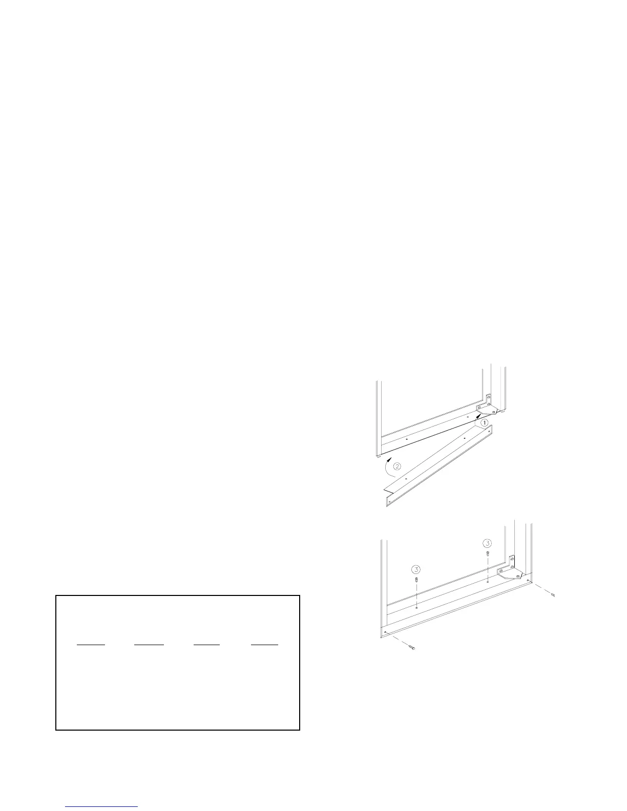
Lower Flange Installation
The lower mountin
flan
e and mountin
screws
are located in a clear plastic ba
positioned in the
coils at the rear of the refri
erator. After removin
the
plastic ba
, slide the refri
erator partiall
into the en-
closure and attach the lower mountin
flan
e. Install
the lower mountin
flan
e b
maneuverin
it under
and behind the bottom hin
e and secure with the
screws provided. Refer to Fi
ure 7.
Do not omit in-
stallation of the lower mounting flange. This
flange is part of the combustion seal.
Securing the Refrigerator
Secure the refri
erator with screws throu
h the
mountin
flan
e holes at the front of the refri
erator
and the holes at floor level at the rear of the refri
-
erator. Screw covers are provided to cover the front
mountin
flan
e holes.
TABLE 2
REFRIGERATOR CUT-OUT OPENINGS
INCHES
Model
662,3
6162,3
682,3
6182,3
652,3
6052,3
Hei
ht
52 7/8
52 7/8
59 7/8
59 7/8
43 1/4
43 1/4
Width
23 1/2
23 1/2
23 1/2
23 1/2
23 1/2
23 1/2
Depth
24
24
24
24
24
24
Fi
ure 7
8