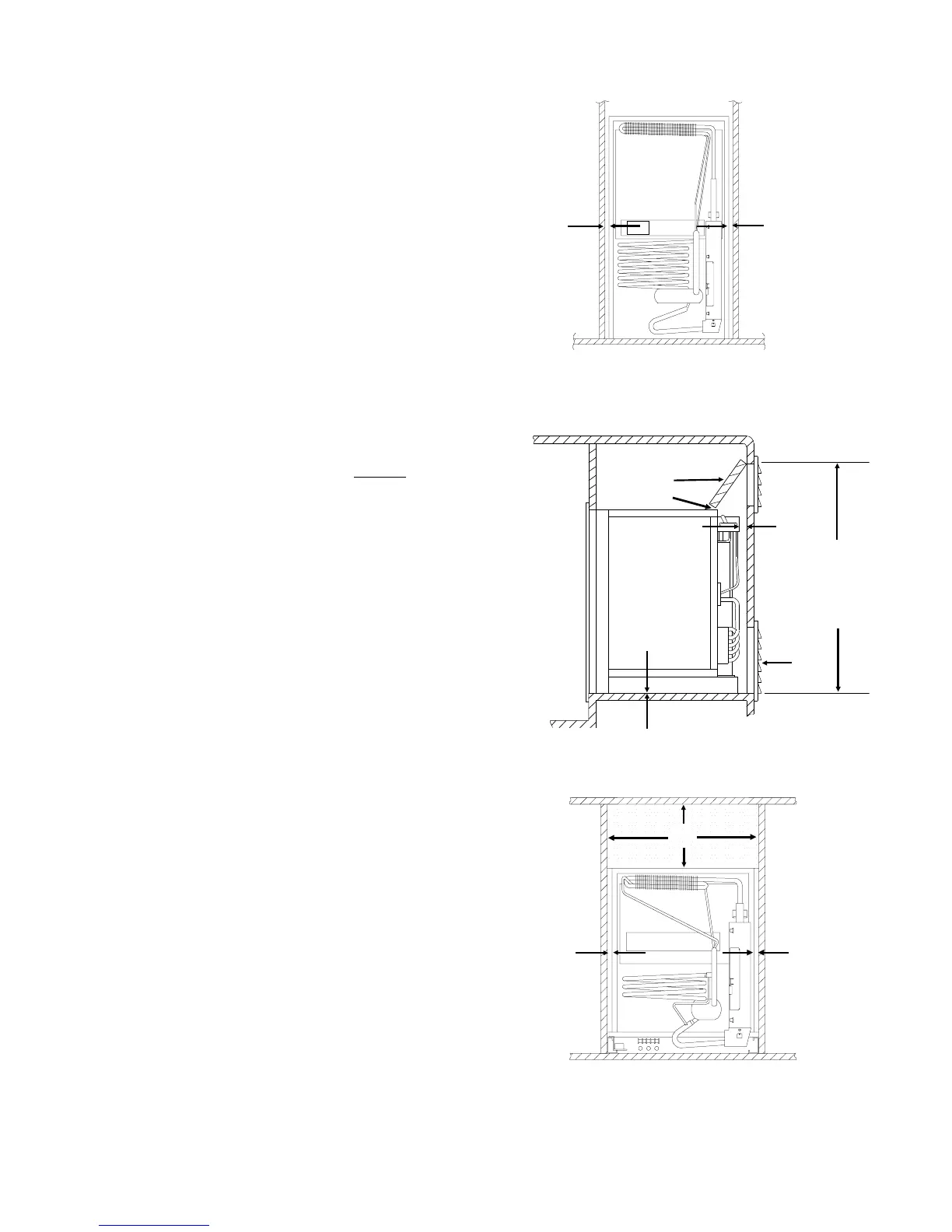
Side Wall Clearance - Figure 4
1. Fi
ure 4 illustrates the re
uirement to minimize
the clearance at the sides of the refri
erator.
The clearance is not to exceed 1/2 inch. Side
clearances in excess of 1/2 inch must be either
filled with Fiber
las battin
or blocked with pan-
elin
, etc.
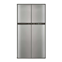
Upper Side Wall Exhaust Vent For Mod-
els 6052, 6053, 652, and 653 ONLY
Figure 5 and 6
1. Area above refri
erator blocked
baffled
off to
prevent trappin
of hot air above the refri
era-
tor.
2. 0 - 1/4 inch clearance at the top of the refri
-
erator.
3. Upper Side vent Location. See Table 1 for vent
dimensions,
4. 0 - 1 inch clearance at the rear of the refri
era-
tor.
See Fi
ure 3 when clearance exceeds 1
inch
.
5. Intake
lower
vent installed flush with the sur-
face on which the refri
erator is mounted.
6. O inch clearance at bottom of refri
erator.
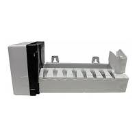
Top and Side Wall Clearance
1. Top baffle fills the total area above the refri
-
erator an is properl
ali
ned with the side wall
construction.
2. 0 - 1/2 inch at the sides of the refri
erator.
50 1/2 " for
upper side
vent openin
.
3
6
4
5
2
1
2
Fi
ure 5
1
B
1
Fi
ure 4
1
2
Fi
ure 6
7