Do you have a question about the Norcold 683 and is the answer not in the manual?
| Brand | Norcold |
|---|---|
| Model | 683 |
| Category | Refrigerator |
| Language | English |
General safety guidelines for the unit and its surroundings, including fire safety.
Safety precautions related to the highly flammable LP gas system.
Importance of ventilation and carbon monoxide risks from exhaust gases.
Safety measures for AC and DC electrical connections and wiring.
Warnings and precautions regarding the refrigerant system, handling, and potential hazards.
Safety advice against installing door locks that could entrap children.
Precautions for safely lifting and handling the refrigerator unit.
General guidelines for installing all refrigerator models, including ventilation and clearances.
Details of certified vent kits required for installation and their compatibility.
Requirements for optimal and optional construction for ventilation.
Specific clearance requirements at the rear of the refrigerator for efficiency.
Guidelines for ventilation above the refrigerator, including roof jack placement.
Minimum side clearance requirements and baffle usage to prevent air blockage.
Compliance with ANSI, AGA, CGA, and various national/local codes for installation.
Instructions for attaching the lower flange, crucial for the combustion seal.
Steps for securing the refrigerator using screws and mounting holes.
Connecting the 120V AC power cord to a grounded receptacle.
Connecting the 12V DC supply, including polarity and wire size recommendations.
Specifics on operating the refrigerator using 12V DC power for 3-way models.
Key considerations and limitations for using 12V DC operation in 3-Way models.
Information on Hypot testing and precautions for protecting the 12V DC circuit.
Steps to remove doors for reversing the swing, including hinge pin removal.
Detailed steps for removing and repositioning hinge brackets for door swing reversal.
Instructions for moving the travel latches to the opposite side for door reversal.
Steps to align doors, check seals, and adjust travel latches after reversing swing.
Essential conditions required before starting lighting instructions, including 12V presence and switch settings.
Step-by-step guide to start the refrigerator in Auto Mode.
Step-by-step guide to start the refrigerator in Gas Mode.
Procedures for shutting down the refrigerator in Gas or Electric modes.
Detailed steps for initiating Auto Mode operation with 3-Way models.
Detailed steps for initiating Gas Mode operation with 3-Way models.
Steps to select and operate the refrigerator in DC mode.
Procedures for shutting down the refrigerator in all modes for short or long durations.
Explanation of the lighted display indicators for AC, LP, X, and DC modes.
How to set and use the thermostat for temperature control.
Function of the High Humidity/Storage switch and its impact on operation and battery drain.
Further details on controls, including cautions and electronic ignition features.
Information on 12V DC current draw and its effect on battery life.
How to set and use the thermostat for temperature control.
Function of the High Humidity/Storage switch and its impact on operation and battery drain.
Information on 12V DC current draw and its effect on battery life.
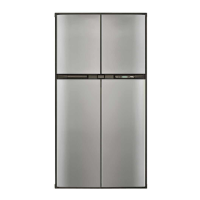
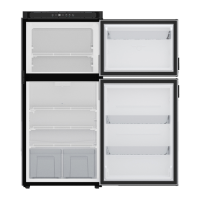
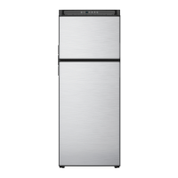
Identifies the location of the Mode Control panel, thermostat, and switches.
Notes on refrigerator performance and leveling during vehicle transit.
Description of the built-in door latch and its function during transit and normal operation.
Explains the AUTO, GAS, and DC modes of operation for the Mode Selector.
How to check and ensure proper door sealing for cooling efficiency and frost prevention.
Procedure for defrosting the refrigerator and cleaning the interior.
Instructions for cleaning the refrigerator's interior and exterior surfaces.
Procedure for replacing the interior light bulb.
Steps for properly shutting down and storing the refrigerator.
How to visually check the burner flame for proper operation in GAS mode.
A checklist for regular maintenance and inspection of the refrigerator.
Annual safety and performance check list performed by a qualified service person.
List of parts available for replacement by the owner or service centers.
Specifications on the storage volume for different models.
Essential safety practices for handling LP gas tanks and connections.
Contact information for service or parts requirements.
Diagram showing the pictorial layout of the 2-way wiring system.
Schematic diagram illustrating the 2-way wiring connections.
Diagram showing the pictorial layout of the 3-way wiring system.
Schematic diagram illustrating the 3-way wiring connections.