Important Points Regarding Battery-Powered
Sources
The dual batter
switch or batter
isolator is an important compo-
nent as it permits the alternator or
enerator to char
e both the
accessor
batter
and the vehicle batter
durin
operation of the
vehicle en
ine. However, it limits the current draw of the DC appli-
ances to the accessor
batter
source when the en
ine or vehicle
is idle or stopped. Thus it assures that the vehicle batter
is full
char
ed for startin
the en
ine. The batteries referred to in Fi
ure
3 are two 6 volt
olf cart batteries connected in series to provide
12 volts. Golf cart batteries are su
ested for the followin
rea-
sons:
1. Lar
er plate construction.
2. Deep draw characteristics.
3. Hi
h ampere-hour ratin
.
The standard
olf cart batter
has a ratin
of approximatel
185-
205 ampere-hours. When two of these batteries are connected in
series, the result is 12 volt DC at 185 or 205 ampere-hour capac-
it
.
The DC suppl
to the refri
erator is connected to the ne
ative
post of one batter
and to the positive post of the other batter
.
The power converter or solid state batter
char
er shown in Fi
-
ure 3 is an essential item for batter
-operated s
stems.
The converter is operated on 120 volt AC and should have an
output ratin
of 12.6-l4.5 volts DC at approximatel
20-50 ampere
capacit
. Durin
120 volt operation, the converter is used to
char
e the batteries and to operate the DC appliances. It has the
capacit
to operate items such as li
htin
, water pumps, exhaust
fans, and sanitar
facilities while maintainin
or char
in
the bat-
teries. Char
in
rate varies from 5-20 amperes per hour.
The Norcold dual volta
e refri
erator automaticall
switches from
AC to DC or from DC to AC. When a power suppl
of 120 volts
AC is connected to the vehicle, the volta
e selection rela
is ener-
ized and disconnects the unit from DC operation. This uni
ue
feature assures 120 volt operation when available and permits the
power converter to concentrate it’s char
in
facilities to the batter-
ies or to other DC appliances.
When the AC suppl
is disconnected, the refri
erator automat-
icall
reverts to DC operation. Settin
the On-Off switch to the
"OFF" position will prevent operation on AC or DC.
The followin
are su
estions for efficient operation of the refri
-
erator:
1. The thermostat dial is numbered from 1 throu
h 5, with the
number 5 settin
the maximum coldest position. In order to
conserve batter
power, it is advisable to set the thermostat
dial at the lowest settin
that will provide ade
uate refri
era-
tion. This practice will reduce the runnin
time of the refri
-
erator and draw less current from the batter
. A settin
of 2
or 3 is a normal position.
2. Alwa
s operate the refri
erator on 120 volts AC when avail-
able, especiall
durin
initial start-up or pull-down c
cle of
the refri
erator. Dependin
upon the ambient temperature,
the initial start-up ma
re
uire 1-2 hours of continuous op-
eration before refri
erator temperature are attained and unit
c
clin
be
ins.
3. Never emplo
"
uick-char
ers" to the batter
unless the On-
Off switch is set to the "OFF" position or the 12-volt DC
leads to the refri
erator are disconnected. Possible inverter
dama
e will occur if the hi
h volta
e of "
uick char
ers" is
permitted to ener
ize the DC circuits of the inverter.
4. The use of a commercial 12-volt DC to 120-volt DC solid
state inverter, converter,
asoline or belt-driven
enerator
with 120 volt AC output is not recommended for operatin
the refri
erator unless the manufacture of the foremen-
tioned devices
uarantee the output volta
e to be 120 volts
AC plus or minus 10 percent and the fre
uenc
to be 60
hertz plus or minus one hertz. Devices that cannot meet
the specified tolerances do not hold the re
uired fre
uenc
,
provide poor performance of the refri
erator, and dama
e
the resonance sprin
s in the compressor.
5. When connectin
the refri
erator to the DC suppl
, observe
the correct polarit
. If the polarit
is reversed
positive con-
nected to ne
ative terminal
, the circuit protection will shut
the unit down. The wire leads must be disconnected and re-
connected properl
, and circuit breaker reset.
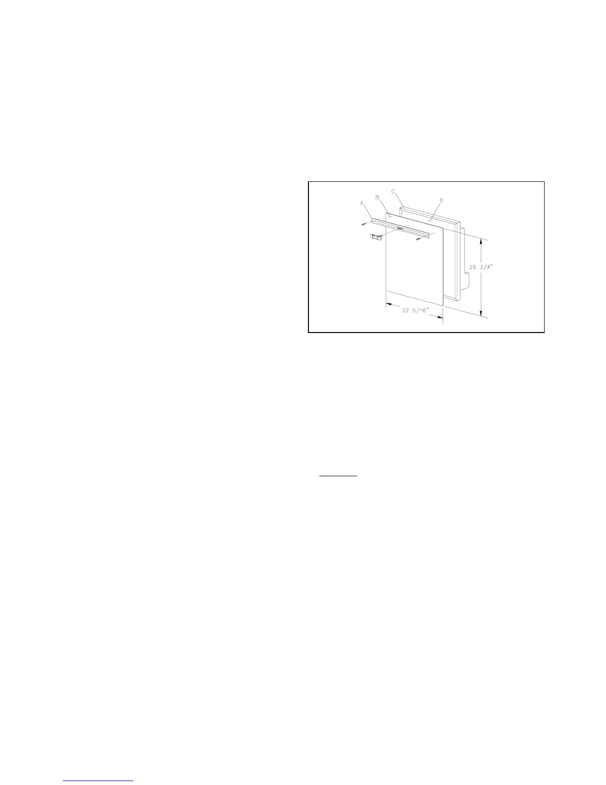
Installation Of Decorator Panel
Prepare the panel b
cuttin
to size as per illustration. Use di-
mensions shown in Fi
ure 4. The maximum panel thickness must
not exceed 3/16"
4.76mm
.
1. Remove the door front decorative strip b
removin
the
screws and pullin
the decorative strip off.
2. Insert one of the vertical sides of the panel
B
into the
roove formed b
the door frame outer flan
e
C
and the
door front.
3. Gentl
flex the panel
B
so that the opposite side ma
be
slipped into the correspondin
roove.
4. Slide the panel
B
downward so that the lower horizontal
ed
e fits into the bottom
roove.
5. Install the door decorative strip
A
to cover the
ap be-
tween the top ed
e of panel
B
and door frame
C
. Se-
cure with screws.
CAUTION: DO NOT OVER TIGHTEN SCREWS.
Fi
ure 4
6
 Loading...