3 Display, operation and options
BU 0240 en-US-4920 51
Pos: 18 9 /Anlei tung en/El ektr onik/FU und Star ter/3 . Anzei ge, Be dienu ng und Op tione n/Bedi enu ng [SK 1xx E, 2xx E, -FDS] /Bedi en- u nd P aram etr ier box en, Ver we ndu ng_ 01 [ SK 1x 0E , SK 2xx E, S K xx xE-F DS] @ 48 \mod_1597666648135_14638.docx @ 2663129 @ 35 @ 1
3.1.1 Use of control and parameterization units
All parameters can be conveniently accessed for reading or editing by means of an optional Simple
Box or Parameter Box. The modified parameter data is stored in the non-volatile EEPROM memory.
Up to 5 complete device data sets can be stored in the Parameter Box and then retrieved.
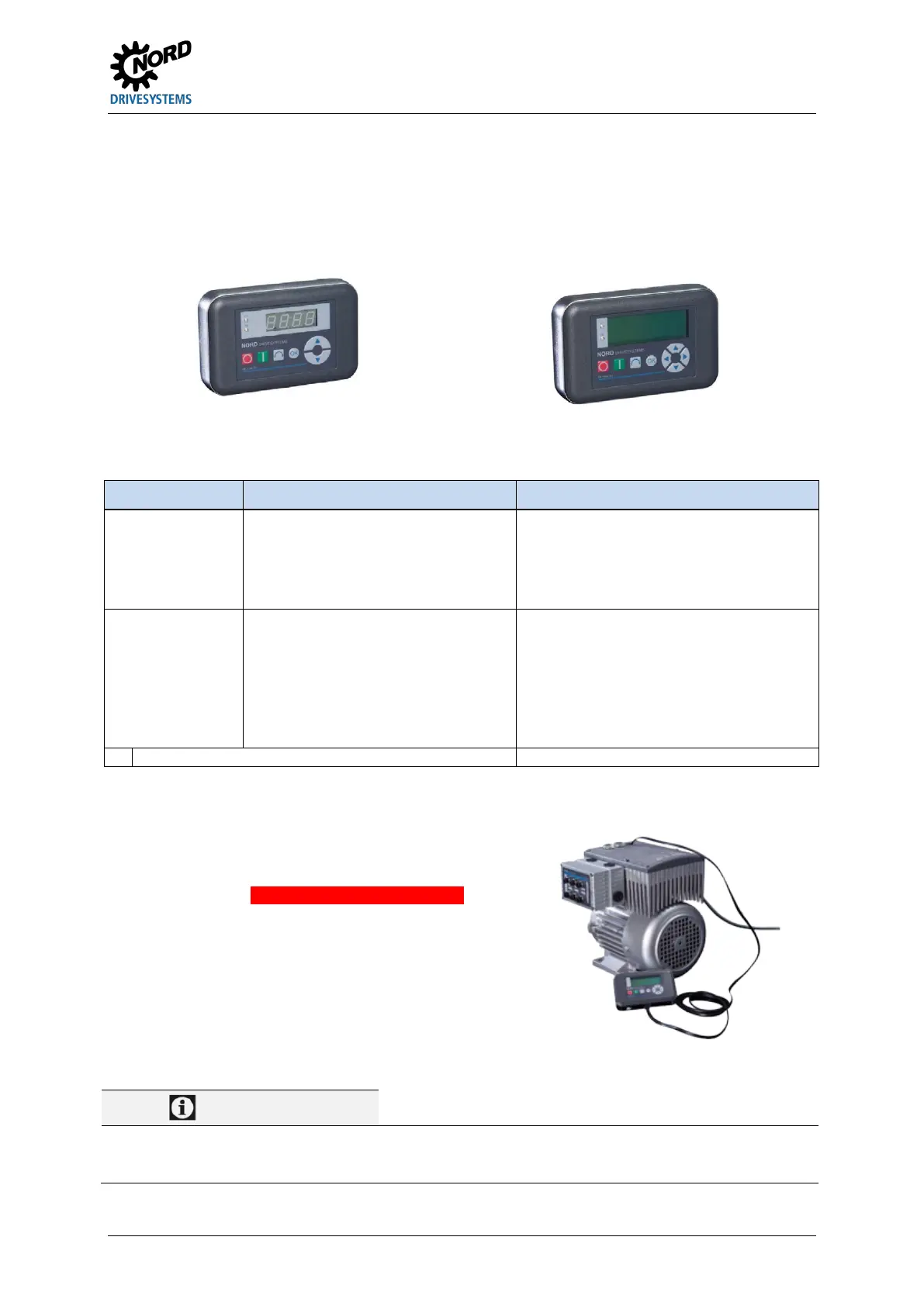
The Simple Box or the Parameter Box is connected to the device through an RJ12-RJ12 cable.
Figure 7: Simple Box, handheld, SK CSX-3H Figure 8: Parameter Box, handheld, SK PAR-3H
Module Description Data
SK CSX-3H
(handheld Simple Box)
Used for commissioning,
parameterization, configuration and
control of the device
1)
.
• 4-digit, 7-segment LED display, membrane
button
• IP20
• RJ12-RJ12 cable
(connection to the device
1)
)
SK PAR-3H
(handheld Parameter Box)
Used for commissioning,
parameterization, configuration and
control of the variable frequency drive and
its options (SK xU4-…). Entire parameter
data sets can be stored.
• 4-line backlit LCD display, membrane keys
• Stores up to 5 complete parameter data
sets
• IP20
• RJ12-RJ12 cable (connection to the
device)
• USB cable (connection to PC)
Does not apply to optional modules such as bus interfaces
Connection
1. Remove diagnostics glass of the RJ12 socket.
2. Establish RJ12-RJ12 cable
control unit and FEHLER - Variable ohne Inhalt.
When a diagnostics glass or a blind plug is open,
make sure no dirt or moisture enters the device.
3.
After commissioning, screw the
or blind plugs back in again and make sure they
are tightly sealed before starting regular operation.
Pos: 19 0 /Anlei tung en/El ektr onik/FU und Star ter/3 . Anzei ge, Be dienu ng und Op tione n/Bedi enu ng [SK 1xx E, 2xx E, -FDS] /Bedi en- und P aram etr i erbox en, Ver we ndu ng_ 02_IN FOR MA TION _Dr ehm om ent [SK 1xxE, SK 2x xE, SK xxx E-FDS] @ 4 2\mod_1590584836809_14638.docx @ 2628659 @ @ 1
,
Diagnostic caps’ tightening torques
The tightening torque for the transparent diagnostic caps (inspection glasses) is 2.5 Nm.
Pos: 19 1 /Allg emein/ Allg emeing ültig e Mod ule/---------Sei tenum bruc h k omp akt --------- @ 13\mod_1476369695906_0.docx @ 2265496 @ @ 1
 Loading...


