3
Series EPC-30 Firmware Upgrade Kit
E 1999 Nordson Corporation
All rights reserved
331 181A
Issued 3/99
Manual 66--EPC30--IS--06 (formerly 46-442)
Follow this procedure to replace the firmware chips. Both chips must be
replaced.
CAUTION: Risk of equipment damage. Make sure you are
properly grounded, or touch a grounded a surface, before
performing this procedure. Static discharge can damage the
firmware chips.
1. Make sure you are properly grounded, or touch a grounded surface,
to remove static discharge from your body.
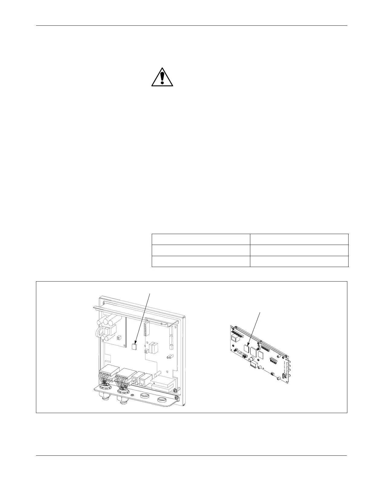
2. See Figure 2. Use the chip removal tool from the service kit to
remove the firmware chips from
S U6 on the main control board (1)
S U3 on the display board (2)
NOTE: If your unit does not have an operater panel, discard the
display board chip.
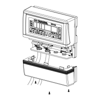
NOTE: The display board is located behind the operater panel
assembly or the remote operater panel.
3. Install the new chips as directed in the following table. Make sure the
notched corner of the chip is aligned with the notched corner of the
connector.
Chip Part Number
Installation Location
277 837 U6 on the main control board
277 845 U3 on the display board
5742112A
2
1
Fig. 2 Replacing the Firmware Chips
1. Firmware chip on main control board 2. Firmware chip on display board
e
ac
g
he
a
eCh
 Loading...