ertical Vent Termination - PVC, CPVC or PP Material
Horizontal Vent Termination - PVC/CPVC Material Only (when using PVT-HL termination)
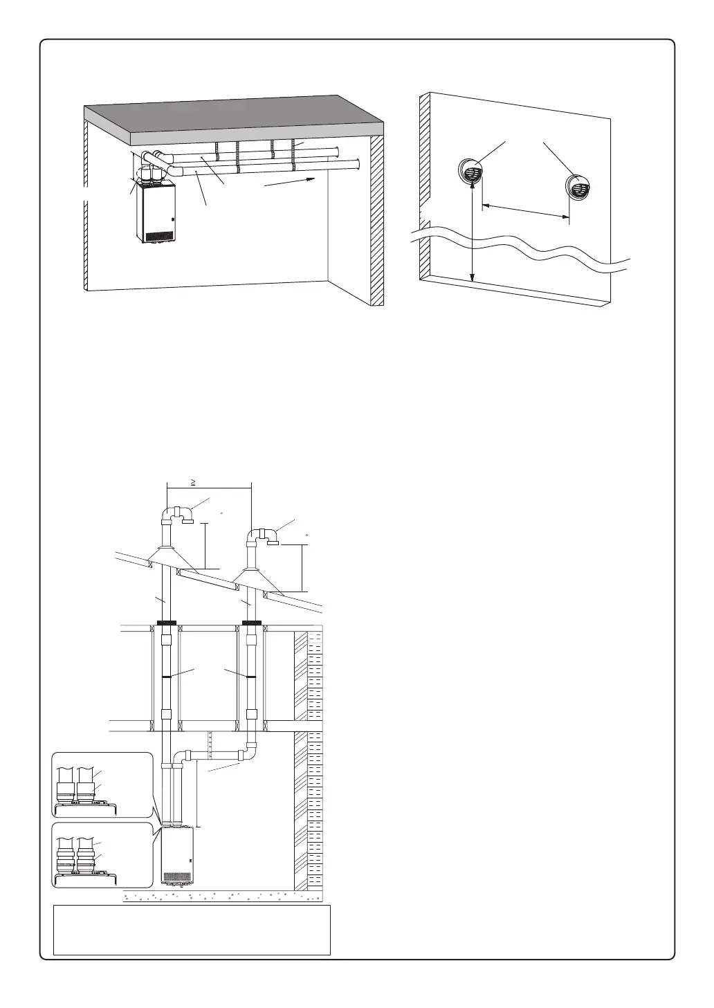
Hanger
Straps
**1' mini
* Not supplied with water heater,
order separately.
mum recommended,
but not required.
3 ft. Min.
Firestop Firestop
Firestop/Support
Roof
Flashing
Roof
Flashing
Hanger
Strap
**1'
Minimum
**1'
Minimum
Support
Slope vent
Upwards
Intake
Exhaust
Slope the Vent
Upward
12" over
maximum
snow level
12" over
maximum
snow level
Insert Bird
Screen* in
End of 90 Elbow
Storm
Collar
Storm
Collar
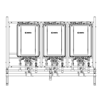
•
Make sure to keep a distance of 3' (0.9m) or wider between the intake and exhaust when installing the vent piping.
If 3’ (0.9m) distance between Intake and Exhaust cannot be ensured, the installation can be carried out only
in the installation method shown in page 16.
•
Terminate at least 12" (300mm) above grade or above snow line.
•
Slope the horizontal vent 1/4" upwards for every 12" (300mm) toward the termination.
•
Use a condensation drain if necessary.
•
In the Commonwealth of Massachusetts a carbon monoxide detector is required for all side wall horizontally vented
gas fuel equipment. Please refer to Technical Bulletin TB 010606 for full installation instructions.
Insert Bird
Screen* in
End of 90 Elbow
When choosing intake and exhaust terminations, you must use the
same type of elbow (i.e. both 90° elbows).
This will help with proper combustion by putting both terminations in
the same pressure zone.
When choosing intake and exhaust terminations, you must use the
same type of elbow (i.e. both 90° elbows).
This will help with proper combustion by putting both terminations in
the same pressure zone.
Insert Bird Screen*
in End of 90 Elbow
3” Min.
Intake
4" (100mm)
Interior Wall
Ceiling
Exhaust
4" (100mm)
Slope the Vent
Upward
Hanger Straps
* 1' Minimum recommended, but not required.
** 4" (100mm) pipe and 4"×4"
couplings
require when using PVT-HL.
* 1' Minimum
When choosing intake and exhaust terminations, you must use the same type of
elbow (i.e. both 90 - elbows).
This will help with proper combustion by putting both terminations in the same pressure zone.
Ӎ 3ft. Min
Intake
Exhaust
Exterior Wall
PVT-HL
4" (100mm)
12"(300mm)
above grade or
above snow line
**
4" x 4" coupling
Exhaust
2" (50mm)
Intake
2" (50mm)
* Not supplied with water
heater, order separately.
** 1' Minimum recommended,
but not required.
The PVC/CPVC elbow may be used in place of
PVT-HL as the horizontal vent termination.
•
•
•
•
•
•
•
•
As illustrated on the left, make sure to keep a distance
of 3' (0.9m) or wider between the intake and exhaust
when installing the vent piping.
Terminate at least 3’ (0.9m) from the combustion air
intake of any appliance and any other building opening.
Enclose exterior vent systems below the roof line to limit
condensation and protect against mechanical failure.
When the vent penetrates a floor or ceiling and is not
running in a fire rated shaft, a firestop and support is
required.
When the vent termination is located not less than
8' (2.4m) from a vertical wall or similar obstruction,
terminate above the roof at least 2' (0.6m), but not
more than 6' (1.87m), in accordance with the National
Fuel Gas Code ANSI Z223.1/NFPA 54 or Natural Gas
and Propane Installation Code CSA B149.1.
Provide vertical support every 3' (0.9m) or as required
by the vent pipe manufacturer's instructions.
A short horizontal section is recommended to prevent
debris from falling into the water heater.
When using a horizontal section, slope the horizontal
vent 1/4” upwards for every 12” (300mm) toward the
termination to drain condensate.
When using 4" PP pipe
4" PP Adapter
ISAAN0404
4" pipe
4" pipe
When using 4" PVC/CPVC pipe
4"x4" coupling
 Loading...