1250$5&
1DYLD$YLDWLRQ$6
,167580(17/$1',1*6<67(0
,167$//$7,21&200,66,21,1*+$1'%22.
2 Tests and adjustments marker beacon
2.1
2.1.1 Preparations
Terminate the
RF OUT terminal with a 50
Ω
load (antenna or dummy). The transmitters are fac-
tory adjusted to 2 watt output power. Let both transmitters run for ½ hour at this power to
achieve a stable working temperature before any fine tuning is carried out.
2.1.2 Configuration settings
Follow this procedure to set the configurations in the Marker Beacon according to desired sys-
tem configuration.
2.1.2.1 General Configuration
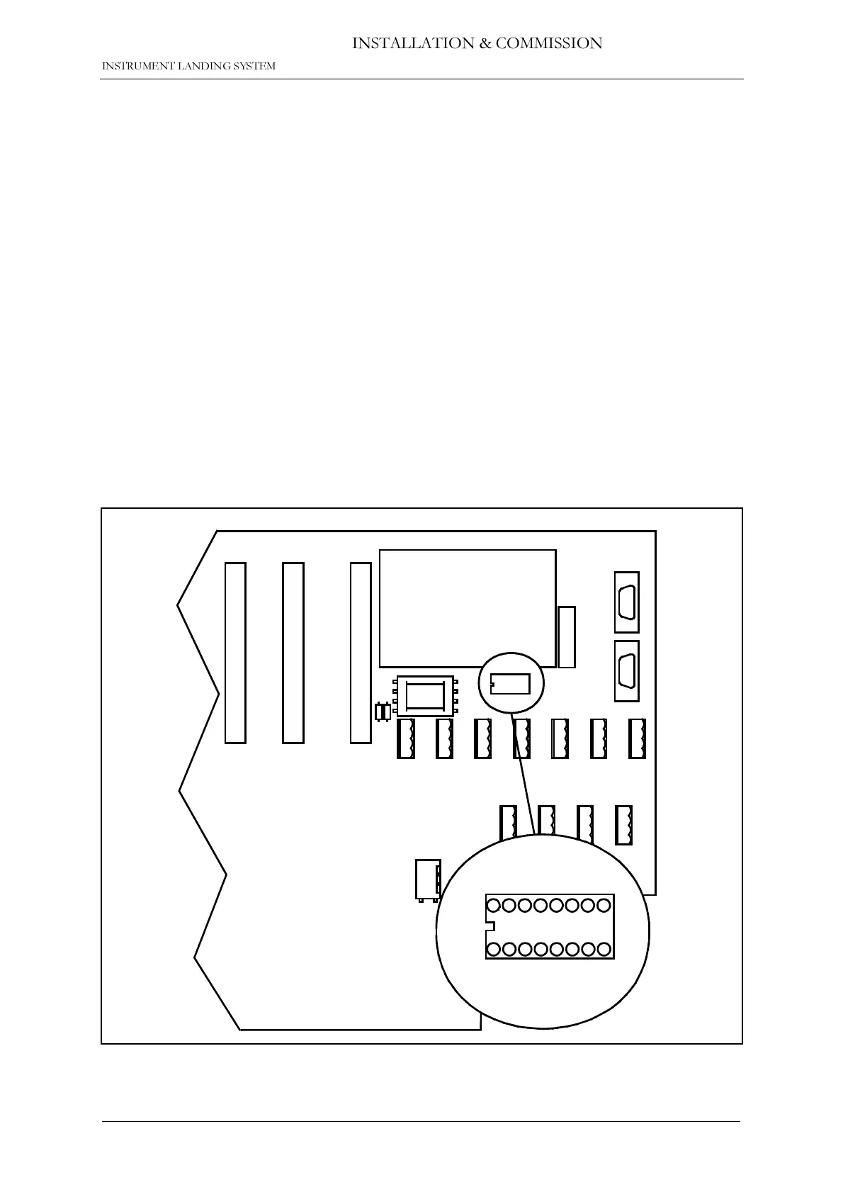
The static control strap on the Connection interface board sets hardware configuration,
remote access configuration and shutdown configuration. Figure 2-1 shows where the static
control strap is located on CI 1376
Figure 2-1 Location of Static Control Strap on CI 1376
DIG PORT A DIG PORT B DIG PORT C DIG PORT D
CI 1376
PB 1378
REMOTE
CONTROL
LINE
TEMP
OUTDOOR
TEMP
INDOOR
AC LEVEL
ANA CHA1
ANA CHA2 ANA CHA3
REMOTE RMM
RS232
REMOTE CONTOL
RS232
CONFIGURATION
S1
S2
S3
S4
S5
S6
S7
S8
CONFIGURATION
S1
S2
S3
S4
S5
S6
S7
S8
HBK797/1



 To Next Page