1250$5&
1DYLD$YLDWLRQ$6
,167580(17/$1',1*6<67(0
,167$//$7,21&200,66,21,1*+$1'%22.
6 Remote Control Connections (TWR)
6.1 Remote Master Connection
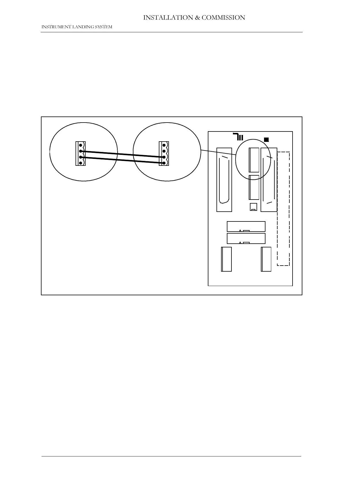
The remote control is connected to the corresponding ILS by connecting the REMOTE CON-
TROL connector on CI1210 (ILS) or CI1376 (Marker Beacon) to P9 on MB1346 as shown in
figure 6-1.
Suitable female connectors are Weidemüller
BLZ-5.08/4
or equivalent. 600 ohms cable
should be used.
Figure 6-1 Remote control to ILS connection
REMOTE
CONTROL
1 - GND
2 - FSK_P
3 - FSK_N
4 - GND
J2
P3
P6
P7
P4
P5
P9
P10
P8
NORMARC
OPTO OUT
2-ALARM (E)
1-ALARM (C)
4-NORM (E)
5-WARN (C)
6-WARN (E)
7-STBAL (C)
8-STBAL (E)
3-NORM (C)
GND
5V
24V
V_DIM
GND
5V
24V
V_DIM
POWER OUT
POWER IN
AUX IN/OUT
SLAVE
DIRECT
INTERLOCK
TXOFF
ALARM
LINE A
LINE B
RX A
RX B
TX A
TX B
SLAVE RS485
J1
ABC
1
5
30
20
25
15
10
ALT.LINK
MB1346
P9
1 - TXOFF
2 - ALARM
3 - LINE_A
4 - LINE_B
CI 1210
on
corresponding
ILS
or
CI 1376
on
corresponding
Marker Beacon
HBK 1135-2



 To Next Page