Calculate the corresponding phase error (electrical degrees) from the formula
: DDM (%) measured in item 1.
: DDM (%) measured in item 3.
(Example values from NM3523B)
Example 1:
Item 1: A1/A12: +4.3% DDM
Item 3: A1+MF/A12: -2.0% DDM (MF in A1)
Example 2:
Item 1: A6/A7: -0.6% DDM
Item 3: A6 /A7+MF: +1.86% DDM (MF in A7)
3.2.5 Phase and amplitude transfer measurement
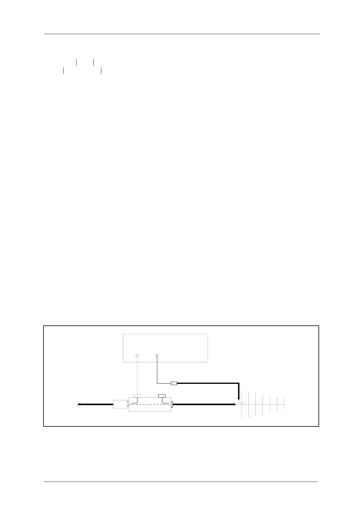
Connect each antenna cable and monitor cable to LPDA load and source respectively. Utilise
a vector voltmeter or network analyser in a test set-up Figure 3-2.
Figure 3-2 Phase and amplitude transfer measurement set-up.
Measure relative transfer phase and amplitude for each Antenna/Monitor return cable in ref-
erence to A1/M1.
ϕ°()
9° DDM
1
DDM
1
DDM
3
+
-------------------------------------------
=
ϕ
9° 4.3⋅
4.3 2.0+
---------------------
4.8°==
ϕ
9° 0.6⋅
0.6 1.86+
------------------------
1.7°==
20dB
AB
VECTOR VOLTMETER
A
n
M
n
From cabinet
CSB BNC o/
Ant.
DIR. COUPL.



 To Next Page