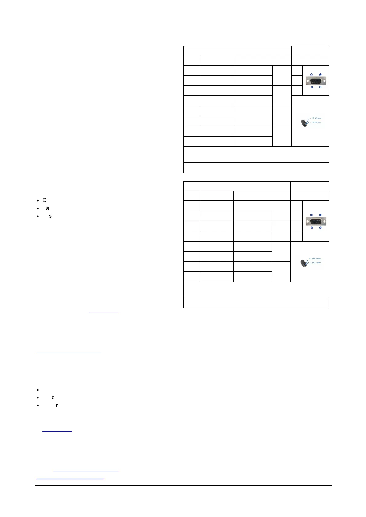
Cables
Our instruments are mostly shipped with RS232
communication. RS422 is used for cables longer than 50
m. The wiring is shown in the tables to the right.
Communication baud rate: 300-115200 (user setting).
Recorder download baud rate: 600/1200 kBaud.
Ensure that the connectors and dummy plugs are
lubricated with dielectric silicone. We recommend 3M
silicone spray. Note that the silicone grease included in
the shipment should be used on the O-rings only.
Analog Input (default for most instruments)
The instrument can read two analog inputs at the same
time. The input range is 0-5V, corresponding to 0-65535
counts in the data file.
Power
·
DC Input: 9-18 VDC
·
Battery DC-input, nominal voltage: 13.5-18 V
·
Absolute maximum DC input voltage: 18.6 V
On-line Interface Box
For cables longer than 50 m the online cable can be
connected to shore to an Interface Box which supplies 48
VDC power and RS422 communication. In the
instrument, a DC-DC converter is used to reduce the
supply voltage to 15 V. Online cable systems are
conceptually quite simple, but in real life, they are both a
technical and practical challenge. We have taken many
years of experience and designed what we believe to be
a very good solution. More information about the Interface
Box can be found on our website.
System Integrator Manual
For more information on how to control a Nortek product
with a non-PC controller, please take a look at the
System Integrator Manual.
Troubleshooting
As most problems are caused by simple mistakes,
please initially check if
·
you have forgotten to power the system
·
the connector has fallen out of the computer
·
you are using the wrong serial port
Nortek online
At our website you will find technical support, user
manuals, and the latest software and firmware. General
information, technical notes, and user experience can
also be found here.
Email: inquiry@nortekgroup.com for general inquiries or
support@nortekgroup.com for technical support.

 Loading...