13
change speeds during start-up, shut down, when thermostat
inputs change, and when the duct static pressure changes
(vents closed or opened, filter clogging, etc.). The air handler
is configured by setting the selector switches and removing
jumper connectors.
Basic Heating Airflow for Variable & Fixed Speed
Fixed & variable speed motor control boards (Figure 17
(page 27) & Figure 18) contain a set of dip switches for
setting the blower speed. For B6EM models, pins 1-4 set the
speed for heating. For B6VM models, the A/B switch must
be set for the appropriate cabinet size (either setting can be
used for C-size cabinets). The airflow is set automatically
based on the amount of installed heat. To determine the
appropriate switch settings for your installation, see Table
7, (page 18), or Table 10, (page 20).
Basic Cooling / Heat Pump Airflow for Variable & Fixed
Speed
The basic cooling/heat-pump airflow is controlled by setting
switches 5 - 8 on the motor control board (mounted on the
blower). All airflows for other modes of operation (except
electric heat) are determined by this basic setting. FAN ONLY
would deliver 50% of the selected cooling airflow. Table 9,
(page 19) lists the CFM airflow values recommended for
each nominal system capacity. To determine dip switch
settings, refer to Table 7, (page 18) for FSHE applications
and Table 10, (page 20) for VSHE applications.
• Whenoperatingintheheatpumpmode,ahigherbasic
airflow setting will increase the energy efficiency and
capacity but will also decrease the supply air temperature.
• Formaximumcapacityandenergyefciency,selectan
airflow at or near the top of the range for that nominal
capacity. See Table 9, (page 19).
• Formaximumdehumidication,selectanairownearthe
middle or bottom of the range for that nominal capacity.
Additional information on humidity control can be found
in the Dehumidication Options section on page 11.
• For thermostats with a dehumidier output, use a eld
supplied wire to connect the thermostat’s dehumidifier
output to the terminal marked DHUM. The thermostat
should be set so that the DHUM output should be high
(energized) when dehumidification is needed. See also
Dehumidification Options section.
IMPORTANT! If coil icing is observed, the basic cooling/
heat-pump airflow selected may be too low. Verify the setting
selected is within the range shown in Table 9 and that the the
system is properly charged. Please refer to the instructions
supplied with the outdoor unit. If icing continues to occur,
raise the selected airflow one or two steps.
NOTE: Variable speed air handlers with SEER ratings higher
than 15 are matched with a 2-stage cooling outdoor unit.
They are programmed to operate at 75% of the selected
airflow while the system is in the lo-cool mode and 100% of
the selected airflow while in hi-cool mode.
Units with an FSHE control scheme (B6EM and 5 ton B6BM
units) have a control board that includes a 7 segment display
to help the installer identify what mode the air handler
is running in as well as troubleshooting if the unit is not
functioning properly. Table 2, (page 13) contains a list of
the codes that may appear on the 7 segment display. The
display code will only show what mode the air handler is
currently in. There is not a history of fault codes that have
occurred in previous operation.
TROUBLESHOOTING
If the air handler fails to operate, check the following:
• Istheelectricturnedon?
• Isthethermostatoperatingproperly?
• Aretheblowercompartmentdoor(s)inplace?
• Istheairhandlerdisconnectclosed?
• Hasthecircuitbreakertrippedorthecontrolboardfuse
burnedopen?
• Areanymanualresetswitchesopen?
• Isthelterdirtyorplugged?
• IstheLEDonbothcontrolboardsconstantlyON?Ifnot,
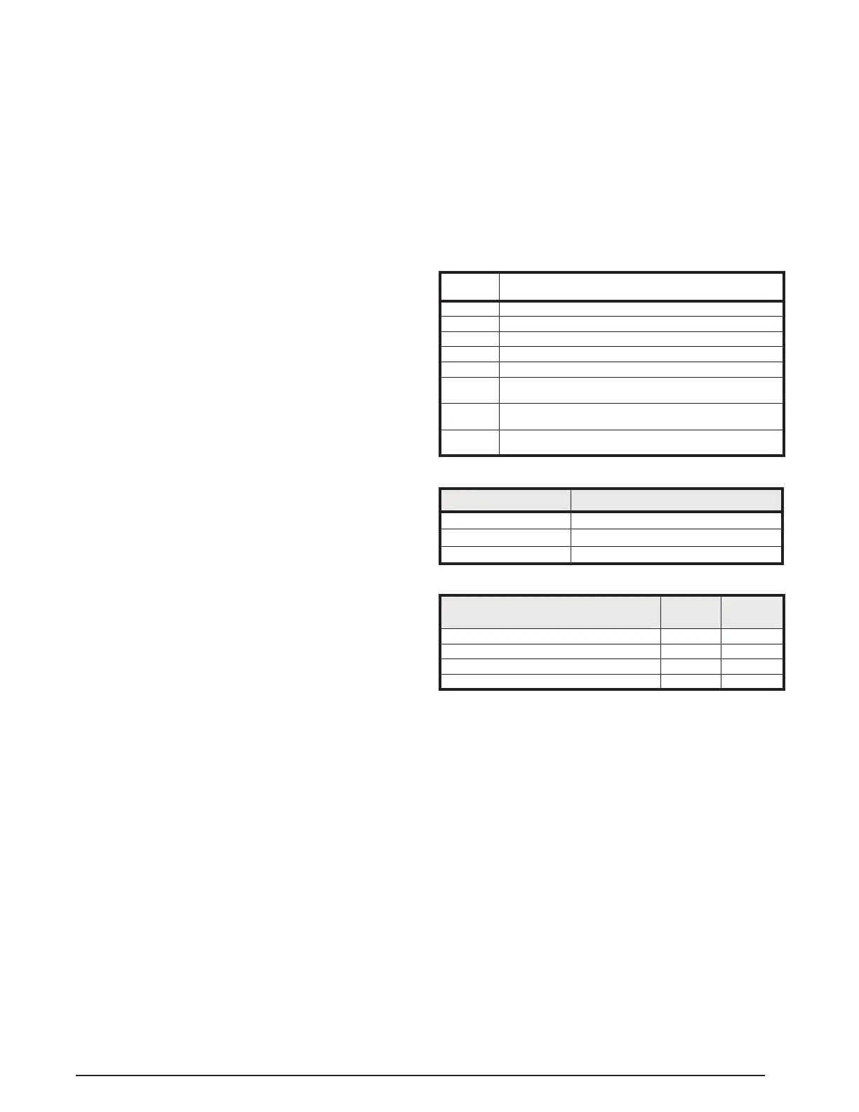
RED LED (AN2) DIAGNOSTIC
OFF Control Fault (No Power)
Flash Blower Fault
ON Normal Operation
Table 3. Air handler Control Board Fault Conditions
Table 2. FSHE Motor Control Board Display Codes
DISPLAY
CODE
CURRENT MODE
-
Standby is a Rotating Segment
C
Cooling Mode (Y input active)
H
Heating Mode (W input active)
f
Circulate Fan Mode (G input active)
d
Dehum Cooling Mode (DEHUM input active along with Y)
I
(one) A Motor Fault has Occurred (BMF active for more than
30 seconds)
t
(lower case t) Over Temperatures (The value of the TS input
has exceeded 80C all outputs are stopped.)
L
Lockout (Ten (10) or more Motor Faults or Over Temperature
events have occurred. All outputs are set to off for one hour.
DIAGNOSTIC FAULT CONDITIONS
FOR VARIABLE SPEED FURNACES
GREEN
LED
RED
LED
Control Fault (No Power) Off Off
Normal Operation On On
Motor Fault On Flash
Communications Fault Flash Flash
Table 4. VSHE Motor Control Board Display Codes
 Loading...