10
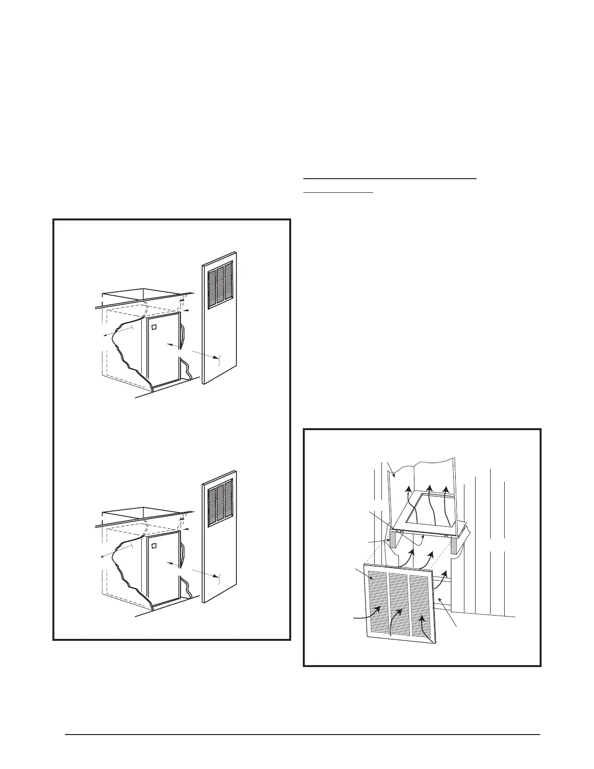
Figure 13. Closet Installation
0" Side
Clearance
to Furnace
Cabinet
Provide min. 235
sq. in. (1516 cm )
open free area in
front or side wall
or in top of
closet door
CLOSET DOOR
6"
(152 mm)
0" Side
Clearance
to Furnace
Cabinet
Provide min. 250
sq. in. (1613 cm
2
)
open free area in
front or side wall
or in top of
closet door
CLOSET DOOR
1"
(25 mm)
Standard Closet Installation
Special 1" Clearance
Upflow Furnaces
The following steps describe installation instructions for
an overhead supply duct system with a return air system
that can be either over the floor (unducted) or through
the floor (ducted).
NOTE: Remove refrigerant line knockouts in furnace only
when installing indoor coil from an air conditioner or heat
pump system.
Refer to instructions supplied with accessory equipment.
Over-the-Floor Return Air System
(Non-Ducted)
1. If floor underneath furnace is made of combustible
material, locate a pan fabricated of non-combustible
material with 1” upturned flanges under furnace return
air opening. See Figure 14.
2. Use optional upflow stand (refer to the technical
specifications literature for part number) with filters or
construct a suitably braced mounting platform in closet.
See Figure 15 (page 11).
3. Route 240V supply circuit(s) and 24V wiring to closet.
See Figure 19 (page 15) for appropriate locations.
4. Position optional coil cabinet onto upflow stand or
mounting platform and secure with three or more
fasteners.
5. Position furnace in upflow mode onto coil cabinet and
secure with two or more fasteners.
6. Use optional upflow duct connector or field supplied
connector to attach furnace to overhead supply duct.
See Figure 15.
7. Install return air grille in closet preferably at same level
as upflow stand or below mounting platform. See Figure
14.
Figure 14. Over-the-Floor Return Air System
Coil Cabinet
Air Filter
Braced
Mounting
Platform
Front
Grille
Non-combustible
Pan or
Enclosure
WALL
FLOOR
rear mounting plate. If mounting plate is not used, an
equivalent method of securing the rear of the unit may
be used as long as it prevents displacement during
transport if used in a manufactured home.
NOTE: The furnace does not need to be positoned
against the rear mounting plate. The tabs will engage
into the slots and allow approximately 1/2” of furnace
adjustment front to back and side to side.
4. Secure front of unit with one or more fasteners at
mounting hole(s) provided or at tie-down tab. See Figure
19 (page 15).
5. See Electrical Wiring section (page 11) to complete
furnace installation.
 Loading...