9
Figure 11. Round Duct Connector Installed
SCREWS
MOUNTING
PLATE
ROUND DUCT
CONNECTOR
14” SUPPLY
CONNECTION
Round Duct Connector Installation
The 14” round duct connector is designed to connect
directly to a 14” flexible duct. NOTE: Flexible ducts must
have a minimum temperature rating of 200° F and meet
all applicable codes and standards.
1. Apply a bead of caulking, mastic, or other approved
sealant around bottom side of connector.
2. Install and center the duct connector in the floor opening.
3. Install the mounting plate under the back side of the
duct connector. See Figure 11. NOTE: Align the screw
holes in both components.
4. Secure the duct connector and the mounting plate to
the wood floor with appropriate size screws.
5. Connect the round supply duct to the underside of the
duct connector and secure them with field supplied
sheet metal screws.
6. Seal all connections with industrial grade sealing tape
or liquid sealant.
NOTE: Requirements for sealing ductwork vary
from region to region. Consult with local codes for
requirements specific to your area.
Alcove Installation
1. Cut alcove rough openings to minimum dimensions
shown in Figure 12. NOTE: The height may increase
depending on the size of the coil compartment.
2. Attach a return air method to the furnace. Depending
on the application, this could be a louvered door coil
box, frame and grille assembly, or an upflow stand with
solid door coil box.
Closet Installation
For proper air circulation, closet installations require a
return air grill installed in the door or a partially louvered
door across the opening. For clearances 6” or greater, the
closet must have an open free area of 235 in
2
minimum.
For special clearances between 1” - 5”, requirements are
a louvered door with a minimum of 250 in
2
(1613 cm
2
) free
area. A fully louvered closet door is strongly recommended
for both installation types. For closet installations, a coil
box is recommended to be installed with the furnace.
If in upflow configuration, an upflow stand will also be
needed. For examples of both types of installations, see
Figure 13 (page 10).
1. Cut return air opening in desired position in door or wall,
preferably above top of furnace. Refer to the Minimum
Unobstructed Airflow section (page 5) for return air
opening requirements.
2. Insert four fasteners, securing grille to door or wall.
Downflow Furnaces
For typical unducted return air downflow applications,
an air-conditioner or heat-pump coil can be installed by
mounting the coil directly on top of the furnace without
adding sheet metal cavities or cutting and trimming wood
panels. Unducted return air systems may be used for
closet or alcove installations.
The steps below describe installation procedures for
an under-the-floor supply duct system with a ducted
or unducted return air system. Duct connectors are
recommended for this application. See Table 2 (page
8).
NOTE: Remove refrigerant line knockouts in furnace
only when installing indoor coil of an air conditioner or
heat pump system. Refer to instructions supplied with
accessory equipment.
1. Route 240V supply circuit(s) and 24V wiring to closet
or alcove. See Figure 19 (page 15) for locations.
2. Remove furnace front door and slide back until bottom
slots in rear of unit engage with both tabs of optional
NARROW
DUCT
NARROW
DUCT
DUCT CONNECTOR TABS
METAL SCREWS
DUCT
FLAP
NARROW
DUCT
DUCT
CONNECTOR
SHEET METAL
SCREWS
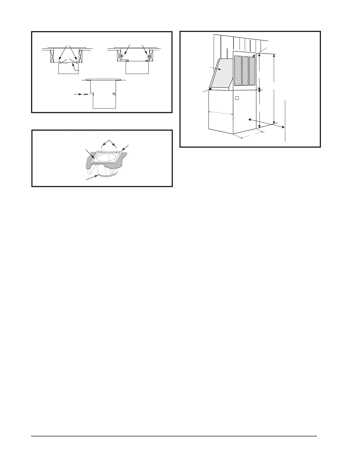
Figure 10. Narrow Ducts
20"
(508 mm)
24 3/4"
(629 mm)
A/C or H/P
Coil
Wall
Coil Air
Filters
Return Air Grille
56"
(1423 mm)
29"
( 737 mm)
27"
(686 mm)
Furnace
Front
18"Nearest
Wall or Partition
Figure 12. Alcove Installation
 Loading...