16
3 AMP
FUSE
COMPRESSOR
OUTDOOR
FAN MOTOR
S
R
C
L2 L1
T2 T1
COMPRESSOR
CONTACTOR
24V
COM
HIGH PRESSURE
SWITCH
240V
LOW
PRESSURE
SWITCH
(SELECT
MODELS
ONLY)
S
R
C
5
4
3
2
1
9
8
7
6
COM NO
NC
F
H
C
RELAY
TRANSFORMER
BLUE
ORANGE
RED
BLACK
BLACK
YELLOW
YELLOW
YELLOW/BLACK
YELLOW
YELLOW/BLACK
PTCR
L1 L2 GND
GROUNDING
SCREW
DUAL
CAPACITION
Y1
W2
E
Y2
O
G
C
R
BLACK
BLACK
5
4
3
2
1
N
G
L
C
BLOWER
MOTOR
BLACK
YELLOW
1. Couper le courant avant de faire letretien.
2. Employez uniquement des conducteurs en cuivre.
3. Ne convient pas aux installations de plus de 150 V a la terre.
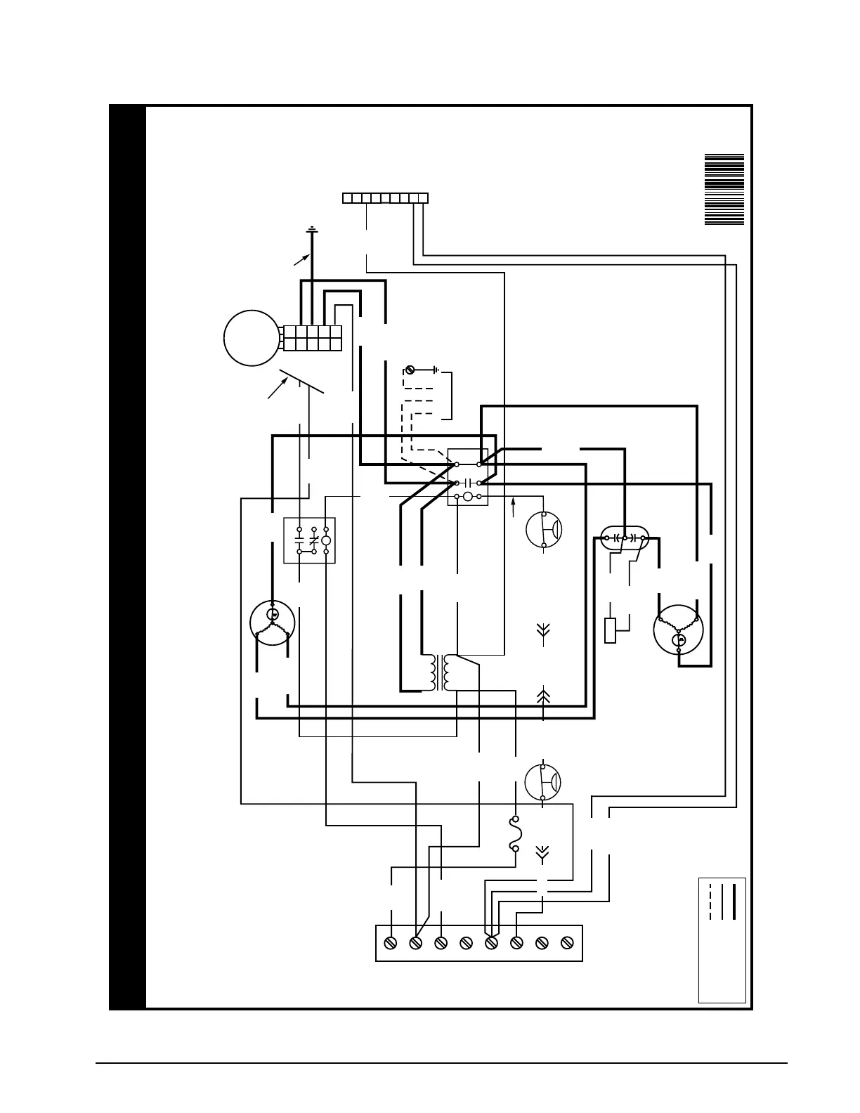
FIELD WIRING
LEGEND:
LOW VOLTAGE
HIGH VOLTAGE
WIRING DIAGRAM
Packaged Air Conditioner - Single Phase
NOTES:
1. Disconnect all power before servicing.
2. For supply connections use copper conductors only.
3. Not suitable on systems that exceed 150 V to ground.
4. For replacement wires use conductors suitable for 105° C.
5. See installation instructions for blower motor airflow settings
and terminal locations.
YELLOW
RED
GREEN
BROWN
ORANGE
RED
RED
RED
BLACK
BLACK
WHITE
ORANGE
GREEN/YELLOW
GREY
YELLOW
RED
YELLOW
10270890
(Replaces 711407C)
06/19
BLACK
BROWN
SEE NOTE 5
Figure 11. Wiring Diagram (1.5, 2, & 2.5 Ton Models)
Wiring Diagrams
 Loading...