7
ELECTRICAL CONNECTIONS
WARNING:
ELECTRICAL SHOCK, FIRE OR
EXPLOSION HAZARD
Failure to follow safety warnings exactly could
result in serious injury, death or property damage.
Improper servicing could result in dangerous
operation, serious injury, death or property
damage.
• Before servicing, disconnect all electrical power
to the indoor blower.
• When servicing controls, label all wires prior
to disconnecting. Reconnect wires correctly.
• Verify proper operation after servicing.
• All electrical connections must be in compliance with all
applicable local codes and ordinances, and with the current
revision of the National Electric Code (ANSI/NFPA 70).
• For Canadian installations the electrical connections and
grounding shall comply with the current Canadian Electrical
Code (CSA C22.1 and/or local codes).
Pre-Electrical Checklist
√ Verify that the voltage, frequency, and phase of the supply
source match the specifications on the unit rating plate.
√ Verify that the service provided by the utility is sufficient to
handle the additional load imposed by this equipment. Refer
to the unit wiring label for proper high and low voltage wiring.
√ Verify factory wiring is in accordance with the unit wiring
diagram Figure 11 (page 16) and Figure 12 (page 17).
Inspect for loose connections.
Line Voltage
• A wiring diagram is located on the inside cover of the electrical
box of the unit. The installer should become familiar with the
wiring diagram before making any electrical connections to
the unit.
• An electrical disconnect must be located within sight
of and readily accessible to the unit. This switch shall be
capable of electrically de-energizing the unit.
• Line voltage to the unit should be supplied from a dedicated
branch circuit containing the correct fuse or circuit breaker for
the unit. Incoming field wiring and minimum size of electrical
conductors and circuit protection must be in compliance with
information listed on the unit data label. Any other wiring
methods must be acceptable to authority having jurisdiction.
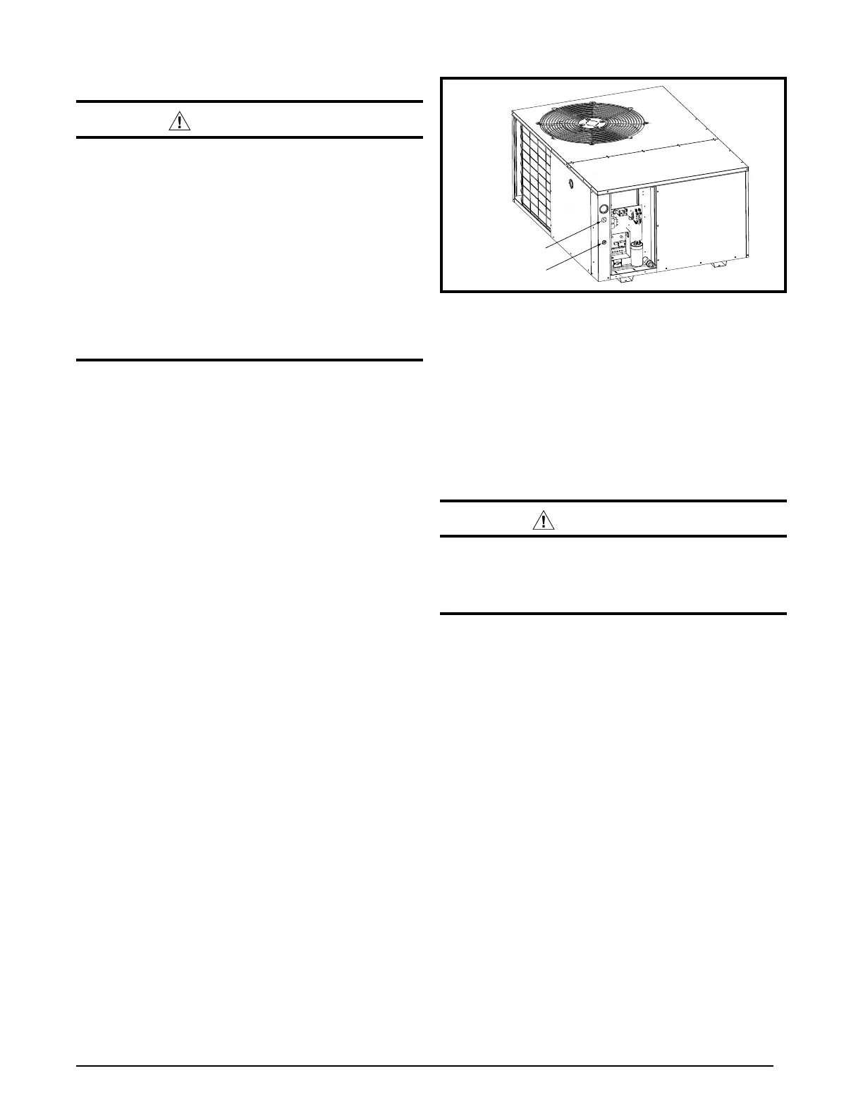
• Provide power supply for the unit in accordance with the
unit wiring diagram, and the unit rating plate. Connect the
line-voltage leads to the terminals on the contactor inside
the control compartment. Extend leads through power wiring
hole (Figure 7). Connect L1 & L2 directly to the contactor.
• The unit requires both power and control circuit electrical
connections. Refer to the wiring diagrams (Figure 11 (page
16) & Figure 12 (page 17)) for identification and location
of unit field wiring interfaces. Make all electrical connections
in accordance with all applicable codes and ordinances.
• Overcurrent protection must be provided at the branch circuit
distribution panel and sized as shown on the unit rating label
and according to applicable local codes. See the unit rating
plate for minimum circuit ampacity and maximum overcurrent
protection limits.
• Use only copper wire for the line voltage power supply to this
unit. Use proper code agency listed conduit and a conduit
Low Voltage
Line Voltage
Figure 7. Power Entry
connector for connecting the supply wires to the unit. Use of
rain tight conduit is recommended.
• 208/230 Volt units are shipped from the factory wired for 230
volt operation. For 208V operation, remove the lead from
the transformer terminal marked 240V and connect it to the
terminal marked 208V.
• Optional equipment requiring connection to the power or
control circuits must be wired in strict accordance of the NEC
(ANSI/NFPA 70), applicable local codes, and the instructions
provided with the equipment.
Grounding
WARNING:
The unit cabinet must have an uninterrupted or
unbroken electrical ground to minimize personal
injury if an electrical fault should occur. Do not
use gas piping as an electrical ground!
This unit must be electrically grounded in accordance with
local codes or, in the absence of local codes, with the National
Electrical Code (ANSI/NFPA 70) or CSA C22.1 Electrical Code.
Ground the air conditioning unit using the green grounding screw
provided in the control panel.
Overcurrent Protection
Overcurrent protection must be provided at the branch circuit
distribution panel and sized as shown on the unit rating label and
according to applicable local codes. Generally, the best fuse or
breaker for any heat pump is the smallest size that will permit
the equipment to run under normal usage and provide maximum
equipment protection. Properly sized fuses and breakers also
prevent nuisance trips during unit startup.
NOTE: If a fuse blows or a breaker trips, always determine
the reason. Do not arbitrarily install a larger fuse or breaker
and do not, in any case, exceed the maximum size listed
on the data label of the unit.
Thermostat / Low Voltage Connections
• The unit is designed to operate from a 24 VAC Class II control
circuit. The control circuit wiring must comply with the current
provisions of the NEC (ANSI/NFPA 70) and with applicable
local codes having jurisdiction. Thermostat connections should
be made in accordance with the instructions supplied with the
thermostat and the indoor equipment.
• The low voltage wires must be properly connected. Route 24V
control wires through the sealing grommet near the power
entrance. See Figure 7. Recommended wire gauge and wire
 Loading...