5
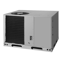
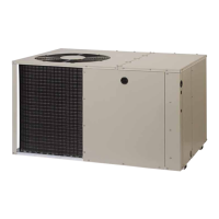
HEAT PUMP INSTALLATION
Unpacking the Unit
It is recommended that the unit be unpacked at the
installation site to minimize damage due to handling.
CAUTION:
Do not tip the unit on its side. Oil may enter
the compressor cylinders and cause starting
trouble. If unit has been set on its side, restore
to upright position and do not run for several
hours. Then run unit for a few seconds. Do this
three or four times with five minutes between
runs.
1. Remove the bands from around the unit.
2. Unfold the top and bottom cap flanges.
3. Carefully remove the top cap and tube.
Minimum Clearances
Minimum clearances MUST be maintained from adjacent
structures to provide room for proper servicing and air
circulation. DO NOT install unit in a confined or recessed
area that will allow discharge air from the unit to re-circulate
into the condenser air inlet, through the coil. See Figure 1.
Service Access Clearance:
Blower access panel side .......................................... 24”
Electrical compartment access panel side ............... 12”
Clearance between overhang and top
of unit .................................................................. 72”
Clearance around condenser coil area to
wall or shrubs (excludes duct panel side) .................. 12”
Clearances to Combustibles:
Combustible base - wood or Class A, B, or C
roof covering material ................................................. 0”
Supply & return air ducts ............................................ 0”
Duct connection side .................................................. 0”
Air Duct System
Air ducts should be installed in accordance with the
standards of the National Fire Protection Association
“Standard for Installation of Air Conditioning and Ventilation
Systems” (NFPA 90A), “Standard for Installation of
Residence Type Warm Air Heating and Air Conditioning
Systems” (NFPA 90B), these instructions, and all applicable
codes. NFPA publications are available by writing to:
National Fire Protection Association, Batterymarch Park,
Quincy, ME 02269 or visit www.NFPA.org on the web.
• Designtheductworkaccordingtomethodsdescribed
by the Air Conditioning Contractors of America (ACCA).
• Thesupplyductsystem(Figure3,page6),including
the number and type of registers, will have much more
effect on the performance of the system than any other
factor. The duct must be sufficiently large to conduct an
adequate amount of air to each register.
• Ductworkshouldbeattacheddirectlytotheunitanges
for horizontal applications.
• Forhighlyresistiveductsystemsitmaybenecessary
to add an additional return air duct and or supply to
achieve maximum performance and prevent coil icing
and refrigerant flood back.
• The heat pump system will not cool or heat the home
if air is lost to the outside through leaks in the duct
system. Ducts that are collapsed or restricted by
foreign objects will also prevent adequate air flow.
• All duct work passing through unconditioned space
must be properly insulated to minimize duct losses
and prevent condensation. Use insulation with an outer
vapor barrier. Refer to local codes for insulation material
requirements.
Unconditioned Spaces
All duct work passing through unconditioned space must
be properly insulated to minimize duct losses and prevent
condensation. Use insulation with an outer vapor barrier.
Refer to local codes for insulation material requirements.
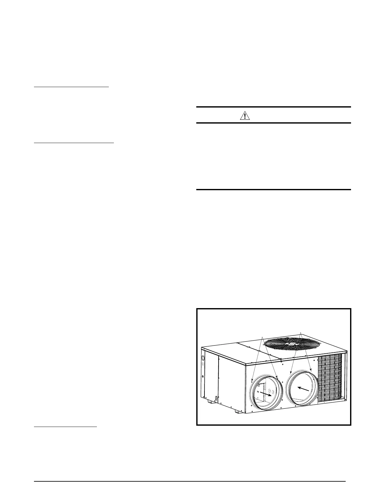
Installing Return & Supply Air Collars
If the supply and return collars are supplied with the unit,
they will be located in the supply duct. They can be easily
positioned over the unit openings (Figure 2) and secured
with sheet metal screws.
• The diameter of the return duct collar is 14”.
NOTE: 2 ton units are designed with 12” returns.
• Thediameterofthesupplyductcollaris12”.
• Before permanently installing the collars, it is
recommended you pre-fit them over the openings first
to determine best fit and alignment.
Figure 2. Return & Supply Air Collars
Transition
Duct Screws
Supply Air
Return Air
Duct
Dimples
The heat pump system will not cool or heat the home
if air is lost to the outside through leaks in the duct
system. Ducts that are collapsed or restricted by
foreign objects will also prevent adequate air flow.
 Loading...